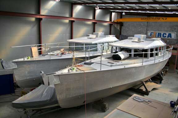
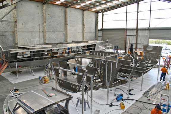
The sun is headed south towards New Zealand, and although spring is a little wet right now, soon it will be summer in the Southern Hemisphere. Progress continues on the first four FPB64s, hulls one and two of which are shown above in the fit out bay (one is on the left with its windows in place). From here on out as the interior goes in the photos will show a degree of visual chaos which will continue right up to the day before launching.
Now to some details.
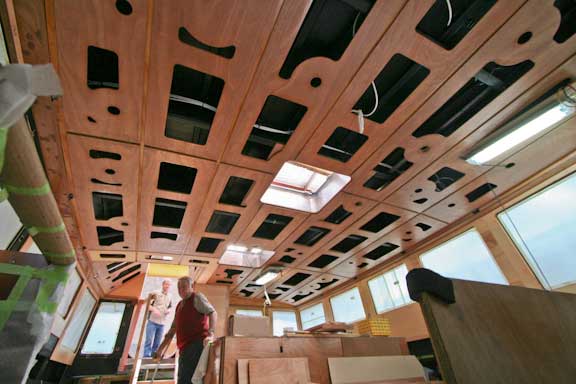
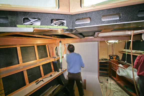
The headliner panels are being fitted to hull number one. The cut outs are to save weight and attenuate noise by allowing sound to transmit through the fabric covered panels.
We are looking here aft, towards the salon entry door.
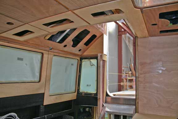
Turning around and looking forward, through the bridge area windows.
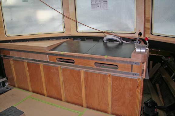
The first of what will eventually be many detailed photos of this area over the next few months. Plenty of space is available to install electronics.
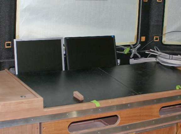
There is space for two 17″ and a wide screen 19″ monitor.These sit in a tray and are angled for optimum viewing.
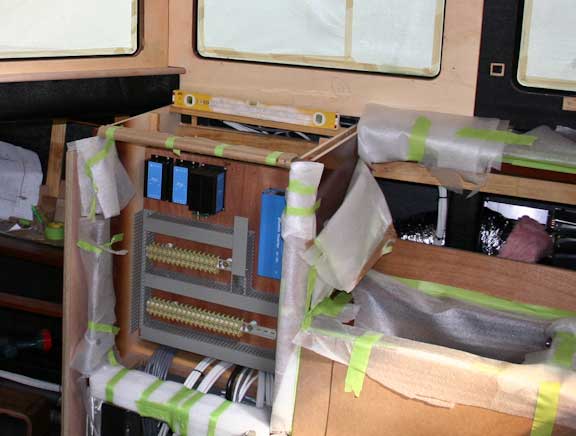
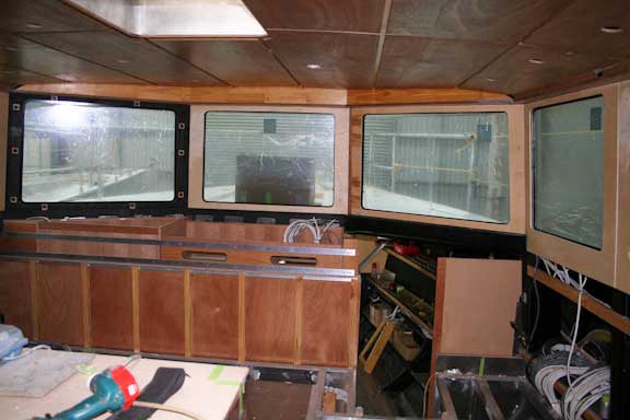
Turning the camera to starboard, this locker will house the AC electrical panel and a small DC panel for breakers related to the bridge area.
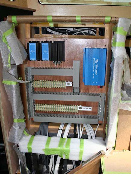
A few weeks from now this will be filled with wiring.
Looking here along the port side of the forward master suite.
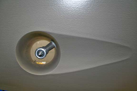
This is a Dorade vent down pipe in the headliner. There will eventually be an “eyeball” to direct air flow. Note the adjustable closure plate, which secures this vent in heavy weather and allows air flow to be throttled.
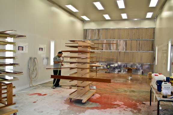
Circa has a huge spray booth, which is in continuous use these days with FPB64 interior parts.
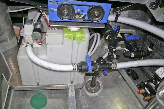
Into the aft end of the engine room. The standpipe bolted to the bottom penetration lifts the plumbing assembly above the waterline. This reduces the chances of leaks, and reduces marine growth within the valves. The plumbing on the right side are various discharges for items like bilge pumps, shower and sink sumps, etc.
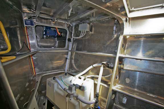
Now to the bow and the forward end of the forepeak. Note the junction boxes for electrical connections to reduce the risk of connections becoming damp.
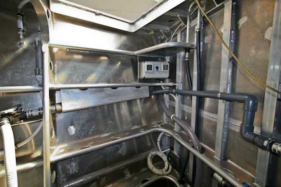
Aft end of the forepeak with the watertight bulkhead isolating the interior on your right.

Note the diverging angles between the leading edge of the rudder and deflector just ahead. This allows the rudder to dropped for maintenance. If these surfaces were parallel the rudder would jam as it was lowered.
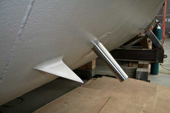
Another deflector, this one ahead of where the stabilizer fin will be installed.
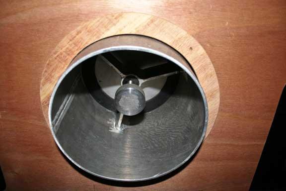
The bow thruster is ready for its props to be attached.
A shot of the fabrication bay with hull three to the left and hull four in the foreground.
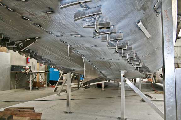
Note the slight tunneling on center and the very fair plating. Keep in mind this is 12mm aluminum, almost 1/2″ thick.
A final detail. The round pipe just below the shear (deck edge) is the air vent for the four fuel tanks in the basement under the great room. This leads to the day tank in the engine room which has its own vent.The day tank collects any foam that may be present and allows it to settle rather than overflow onto the deck.
Posted by Steve Dashew (October 1, 2009)
October 1st, 2009 at 8:58 am
Steve,
I may have missed it, but what is the function of the white tank and pump in the forepeak?
As this boat progresses, it makes every day of work harder! I have scowered over every detail to the point I think I could move through the boat and its systems blindfolded…I am sure you are a proud Papa becasue its beautiful
As my “babyhorse” fund increases I get increasingly anxious:)
all the best
Scott
October 1st, 2009 at 9:32 am
Hi Scott:
The tank and pump to which you refer are for sewage, and connected to the forward head. There is another in the engine room.
October 3rd, 2009 at 5:40 pm
Steve,
I guess I have never seen so much of a waste tank before…so out in the open and easy to service!!
Thanks
November 12th, 2009 at 8:42 am
In From My Old Boat Shop, Weston Farmer speculates that 64 pounds per square foot of waterplane loading is one ingredent to great boat comfort and behavior.
What is the loading for the FPB 64 and the 83 for that matter?
John
November 12th, 2009 at 10:32 am
John:
Simplistic calculations like this make no sense in the real world. Comfort is a much more complex issue starting with the stability curve and location of the crew relative to the pitch and roll centers.