We are often asked why we don’t build the FPBs in fiberglass. We like both fiberglass (properly done) and aluminum, and we have certainly done lots of both over the years. It is just a question of which is best suited to the cruising environment envisaged for this design. Here are a few details to show you why we prefer aluminum for the FPB 64.
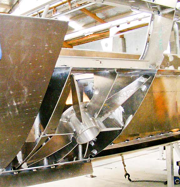
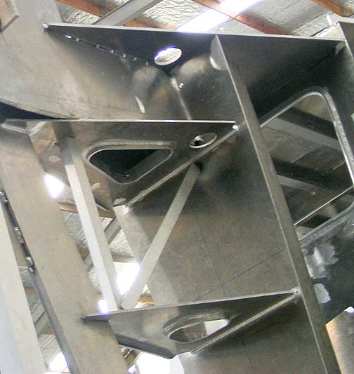
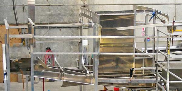
This is the “boss” into which the stabilizer control structure will be installed. Note the heavy aluminum pipe and gussets, all contained within a watertight coffer dam. There is simply no way you can match the strength of this welded structure with secondary fiberglass bonds. For normal working loads over a brief life span, fiberglass is fine. But if you are going to do some rock hopping, dry the boat out on mud flats, and put many thousands of offshore miles on the boat, then we want this highly stressed area to be fabricated from welded aluminum.
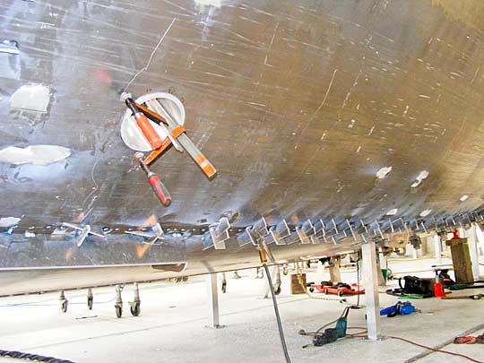
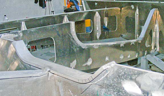
Above is the opposite side of the boat, now with the 12mm hull plate tacked into place (the clamps are holding the plate aligned to the stabilizer boss).
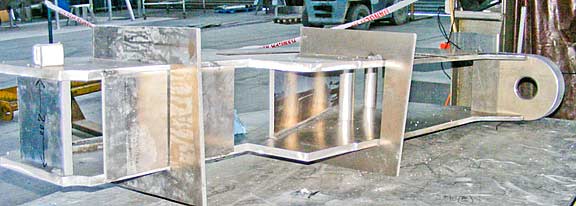
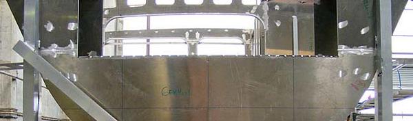
Here the bow roller assembly is starting to come together. 99.9% of the time this would be considered way overbuilt. But if you are caught in a real blow, perhaps in an exposed anchorage, with a foul bottom snagging the anchor chain, it will be comforting to know that this and the rest of the anchoring system are up to the task.
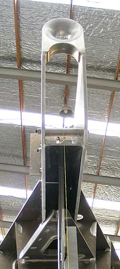
The anchor roller assembly tacked into place. Note the flared anti-chafe fairing on the end. This is normally used with a snubber, but is also here in case the boat is hove to behind a parachute anchor.
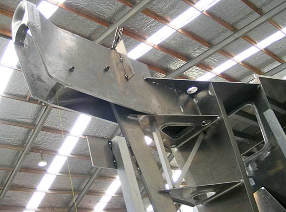
Look at the horizontal webs below the roller assembly. These are connected to the solid stem bar, and reinforce it. They are here for impact resistance.
The centers of the webs are flanged. The flange is to provide resistance to local deflection in a collision. The vertical bulkhead to which these are attached forms the aft end of a collision tank. You can open the bow up to this point, and still keep the forepeak dry.
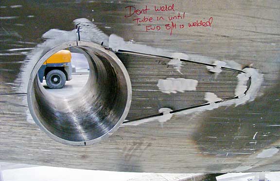
The bow thruster tunnel is another example of the advantage of this approach of boat building. Rather than using secondary bonds with fiberglass, this is a welded pipe. This is the strongest, most reliable approach to installing a tunnel thruster.
This rather confusing photo is of the girder arrangement in the engine room starting to slide into place. The bases to which engine, generator, and other systems tie will eventually be welded to this girder system. This is massively strong. Equally important, it is quiet (makes the structure stiff enough and it does not efficiently transmit noise).
We are looking above at the back end of the hull. The left hand corner is the end of the boarding platform. The space below this is used for systems and bulk oil storage in the engine room. You can also see the mid-engine room ring frame and the outline of the forward engine room bulkhead all the way to the right.
This is the aft end of the hull, part of the transom.
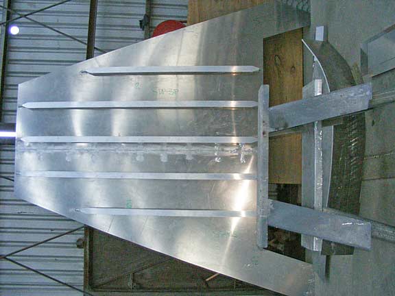
Finally, something equally important if more mundane. This is a forward section of the deck plate, with deck support stringers welded to the underside. Exceptionally strong and – when welded into place – leak-proof. The entire deck and house roof is supported on a series of stringers like these, which are in turn supported on web frames.
Posted by Steve Dashew (September 7, 2008)