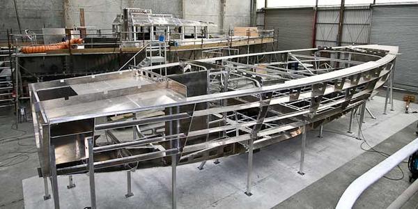
We are almost complete with the metal work on hull number one and hull number two is coming along well.
In this update we will start with a critical component to propulsion efficiency and propeller protection – the skeg.
Our approach is to have the skeg deeper than the prop to provide protection from logs and other debris, and to provide support in a grounding.
The problem is that skegs tend to develop lots of drag, and on traditional heavy displacement vessels create what is called a “wake fraction” which the boat drags along with it. This is very inefficient. The skeg also interferes with the water flow to the prop, reducing prop efficiency.
We wrestled with these details for hundreds of hours on the FPB 83. Now, after 37,000 miles of testing we know we have the basics right. Our fuel burn has been on the low side of projected, indicating the drag and prop efficiency is under control. Equally important, the props remain undamaged even after rolling our share of logs under the boat and operating in lots of ice.
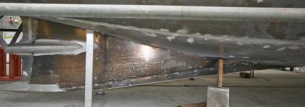
The skeg on the 64 benefits from what we have learned on the 83. It is a sophisticated shape, the volume of which is carefully integrated with the curve of area for the canoe body. We expect minimal wake fraction drag, and excellent water flow to the prop.
The skeg design is not easy to execute and Circa have done a wonderful job on it.
The skeg design is not easy to execute and Circa have done a wonderful job on it.
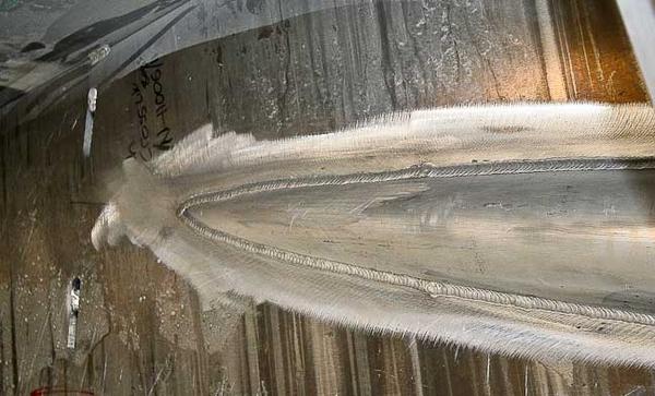
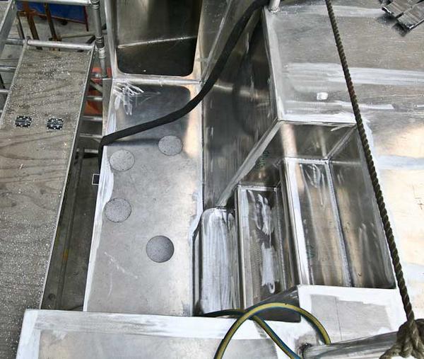
This close up shows how the tube which houses the 2.5″ (62mm) prop shaft exits the skeg. Two compound curves interfacing like this are hard enough to design. There are not many builders who could execute this in aluminum.
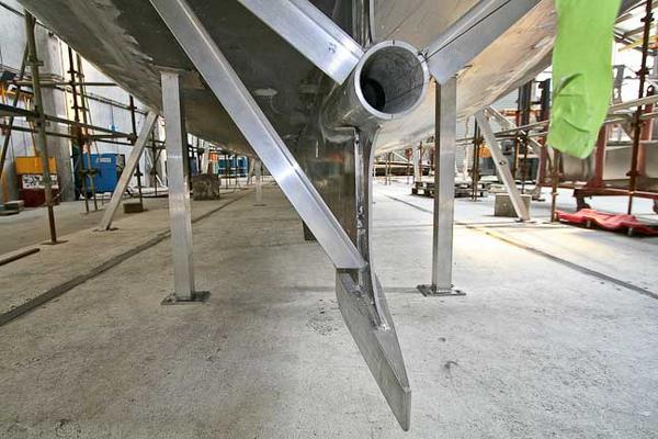
View from astern looking forward. The bottom projection on the skeg is solid. Eventually the steps shown in the plate will be faired to a smooth finish with a sharp trailing edge.
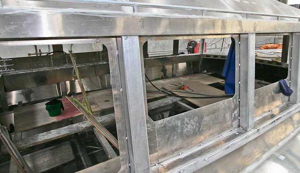
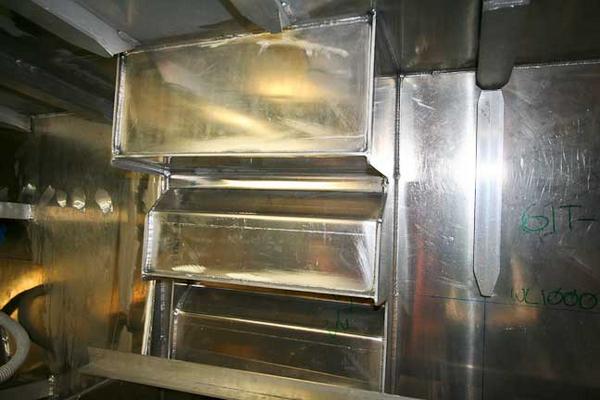
The next two photos show the landings for the 19mm (3/4″) windows which surround the house. Windows are glued into place, using a special structural adhesive. This insures both an enormously strong system, and one which does not leak.
Above we are looking at the aft port corner of the galley. The countertop lockers hide the lower section of the windows, so these are blanked off with aluminum plate.
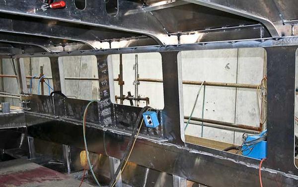
A little later in the schedule and the window landings are fully welded out. Note the holes top and bottom of the mullions.
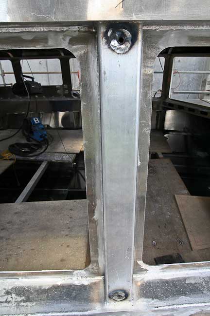
These are for threaded inserts (for 12mm – 1/2″ bolts) which are used with the storm shutter system. They are on each mullion.
Since we started talking about hard to execute metal, how about these stairs from the aft deck down to the swim step?
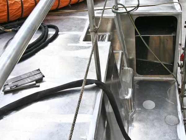
View from the port corner of the deck looking to starboard There are large lockers on each side for outboard engine fuel storage and dive gear.
This view is looking at the stairs from the aft end of the engine room.
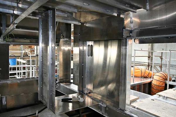
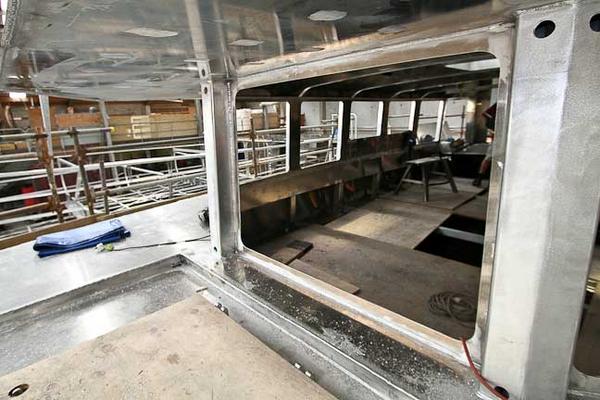
Inside the great room now, looking from the port aft corner (galley) towards the aft entry door. The aluminum “box” will eventually be dressed out to match the interior and form the wet locker/coat closet. Note the slot in the mullion. There is another opposite in the other mullion. These will be used to lead wiring to the masts.
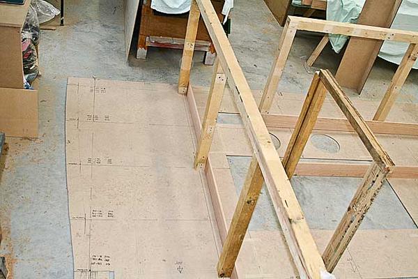
We are entering a new phase. Construction of the interior has started. This is a jig to check clearances and spacing of joinerwork.
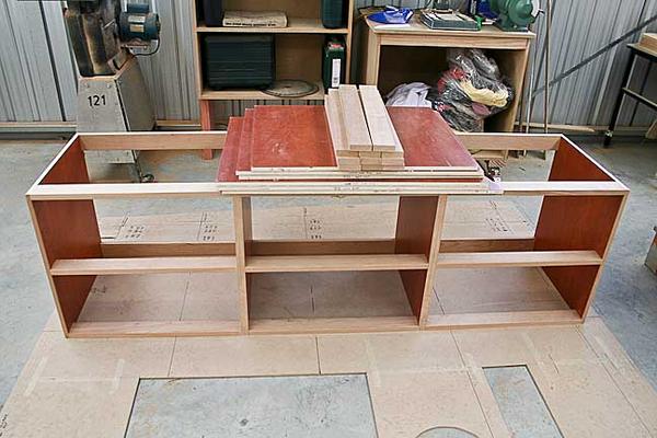
Part of the aft port cabin bunk assembly. This will house the drawers under the bunk and provide support for the mattress. The plywood used for the basic furniture is clad in an HPL (high pressure laminate) which provides an attractive, tough, and easily cleaned surface.
Posted by Steve Dashew (December 7, 2008)