Spring is on its way to New Zealand after a stormy winter, and the first FPB 64 is on its way as well. The second hull is about to start (plate is being cut now). We have been remiss in updating the website, so this is a long, detailed report.
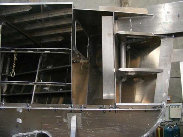
We’ll start with this photo of the bow just before it was closed off with the final topside plate. This shows the structure which supports the centerline girder in a collision, forming a watertight tank in the process. Note the vertical solid round bar from the middle horizontal web. This is the Sampson post which exits through deck and is used for towing and other high-load situations. The second bulkhead forms the aft end of the chain locker, and then you have the storage portion of the forepeak.
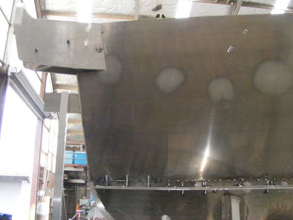
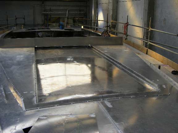
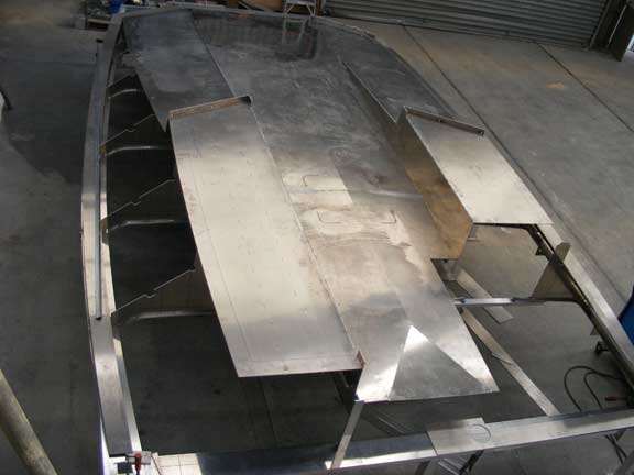
As designers we want the flattest topsides Circa can fabricate (flat is favored for penetrating headseas). There is less than an inch of curvature, yet the results, as you can see above, are exceptionally fair.
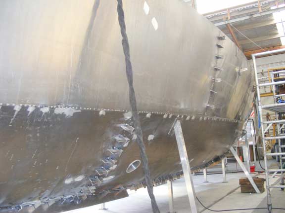
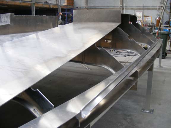
The seam between the 12mm (15/32″) plate of the bottom and 8mm (5/16″) plate of the topsides is shown across the center of the photo.
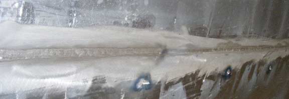
The next step is to weld the exterior of the seam. This is the way welds should look.
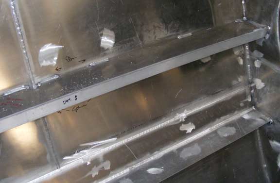
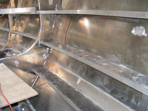
To finish this subject, we are looking above now at the inside of the hull. The seam which is parallel with the stiffening beams is the chine transition we just showed you in the previous photos. A vertical plate seam is also visible. Note the width of the topside stiffener. This is an exceptionally strong framing system, which also integrates well with the interior.
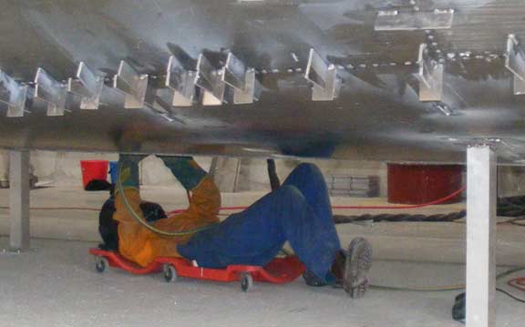
Working overhead – whether welding or grinding as is the case here – is never easy.
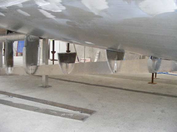
The beginnings of the propeller protection and support skeg. Another massively strong part of the FPB 64. It will also form a deep sump in the engine room.
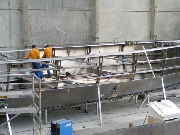
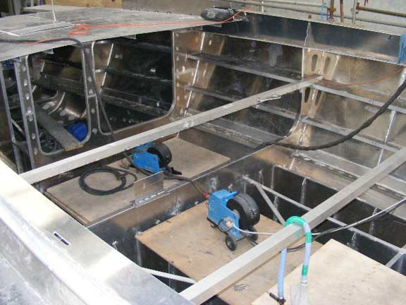
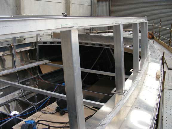
Let’s back up a minute and review the structural system. This earlier photo, with starboard topside plate yet to be installed, gives us a good feel for the framing. There are transverse web frames or bulkheads every 6 to 8 feet (1.8 to 2m) along the length of the hull. In the topside area we have a series of three deep longitudinal stiffeners, which span between the transverse girders. The framing system is significantly stronger than is required by the Lloyds Special Service Rule. It also results in very fair shape, something desirable if you want unpainted topsides.
You can see the three topside stringers above the port side, as they connect to the forward salon/aft owner’s stateroom web frame. On the starboard side these are hidden within the furniture. On the port side the upper two are finished off to match the rest of the interior to form convenient (and attractive) shelves.
This is looking at the aft end of the salon, into what will become the aft guest cabin/office area and through the bulkhead into the engine room. The topside stringers are continuous from one end of the FPB 64 to the other.
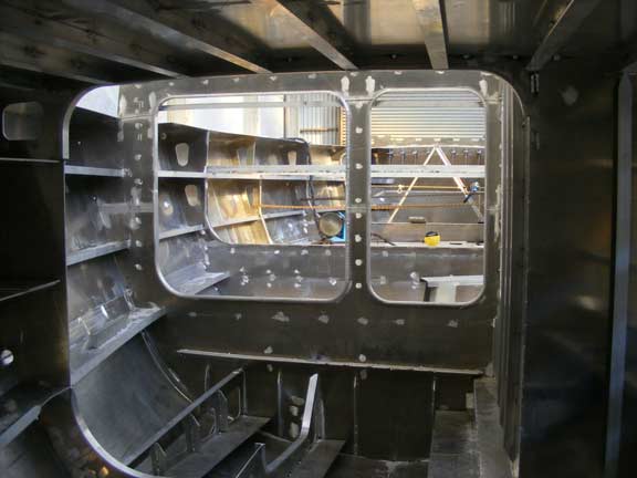
Opposite view now, from the aft end of the engine room forward. The transverse girder in the foreground is centered in the engine room. Next comes the engine room bulkhead which separates the living quarters from the machinery space.
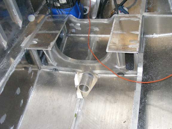
Another engine room detail, this time the aft engine bearers and the propeller shaft tube which runs through the prop skeg.
And the forward end of the engine bearers. The area above the skeg will eventually be opened to form a deep sump.
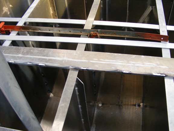
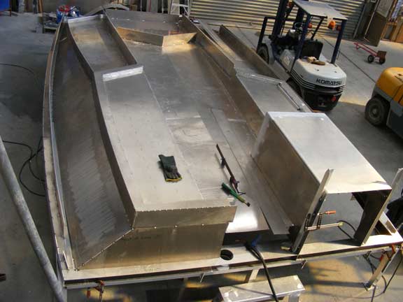
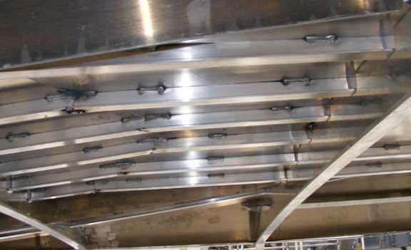
The fuel tanks are located under the salon, and carry a huge amount of liquid. The photo above shows the longitudinal hull girders which are at roughly two foot (60cm) centers down the length of the hull. These are deep, strong, and act as baffles to reduce movement of liquids (and the noise associated therewith).
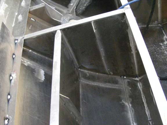
Above, looking into one of the two outboard wing tanks, in this case aft of the stabilizer coffer dam on the port side. The wing tanks are used to adjust side to side trim.
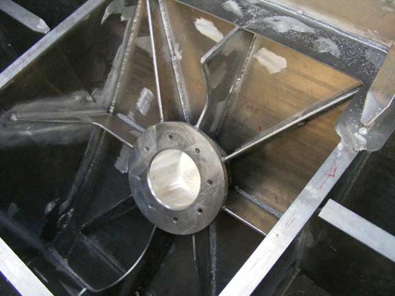
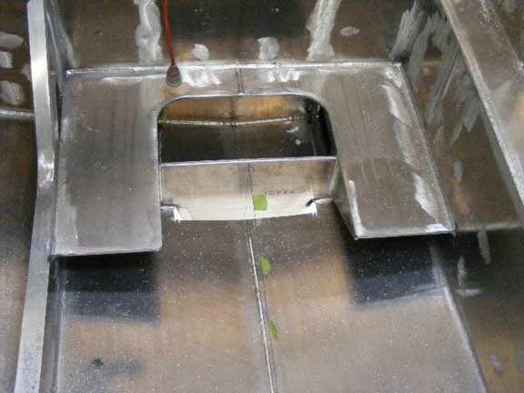
Moving forward in the salon, ahead of the wing tank, we have the support structure for the stabilizer. The stabilizer mechanism bolts to this flange. The load is then spread out into the surrounding hull with eight gussets. This is designed to withstand the thousands of reverse cycle loads which occur each passage with these oversized active stabilizers.
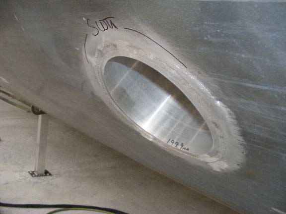
A bottom view of the stabilizer insert welded to the 12mm plate.
The deck is just about finished now. The photo above is looking from the foredeck aft, at what we affectionately call the “pickle forks”. These are coamings which are structural, work as Dorade boxes, and are integrated with the forward awning system.
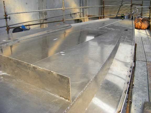
Looking from the starboard deck forward at the pickle forks.
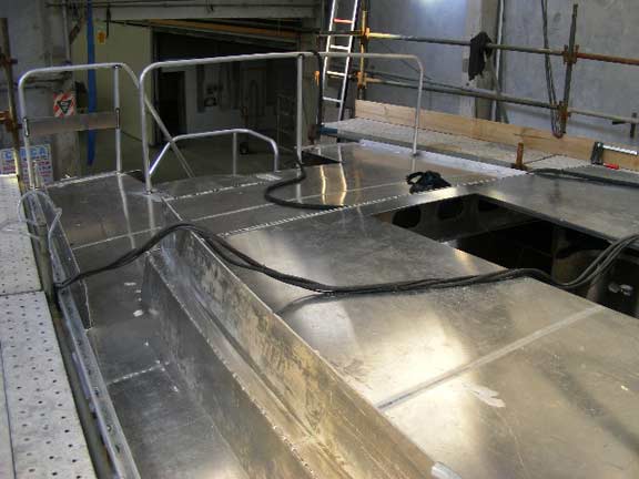
The deck area and coamings over the aft end of the hull are complete as well.
Which brings us to the house mullions. These potentially carry huge loads in a knockdown. The mullions are heavy-walled 4-inch (100mm) extrusions, which begin to tie to the structure of the hull at the top of the coamings.

The mullions run down through the coaming, as you can see here, connecting to the deck and to the upper topside stringer. This forms an enormously strong bond beam.
Possibly the most complex part of the aluminum work is the house roof. This is initially constructed off the boat in a specially built jig. We are looking down at the aft side of the roof here. The port seat is in the center, the fly bridge sole just to the right of the seat.
Looking aft from the port forward corner. Note the transverse ribs which are in line with the mullions.
The roof/flying bridge are almost complete here, ready for trimming and final welding. The structure bottom right is the “scuttle” (top of the entry into the salon from the aft deck).
Here we are looking at the underside of the roof. The deepest beam runs transversely, between mullions. The shallower T’s running across the photo support the upper plate.
The first container of engine room and general equipment has now arrived in New Zealand and shortly the initial layout of this gear will start.
Posted by Steve Dashew (October 7, 2008)