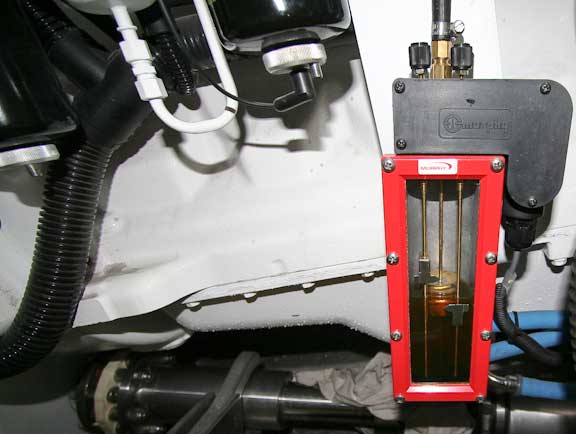
The first FPB 64 reached a significant milestone this week, indicated by the photo above. The red Murphy sight gauge with level alarms provides an important clue. There is now oil in the engine. But wait, there’s more.
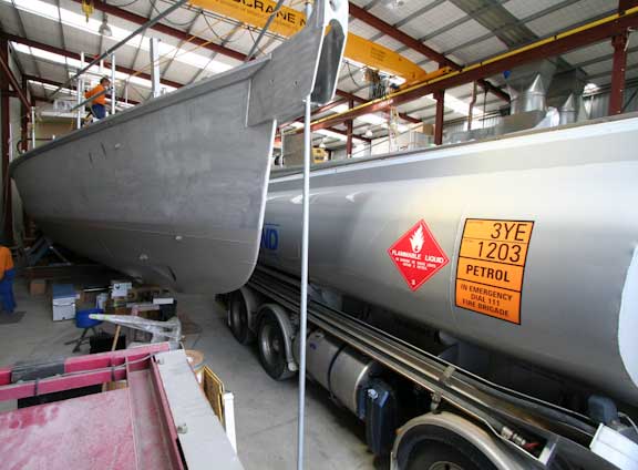
Can you guess what this truck is doing?
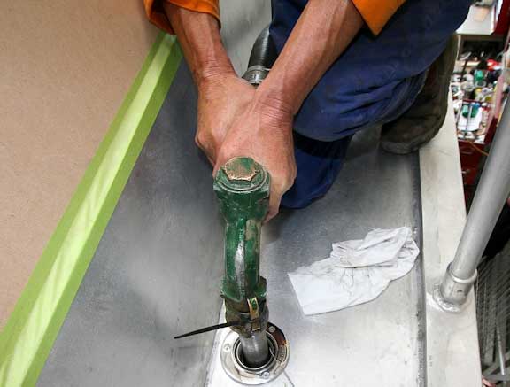
They are loading 1500 liters (400 gallons) of diesel onboard with which Circa will begin testing the fuel system, along with running the engine, genset, and diesel heater.

This always an exciting point for us on a new design as it is a definite indicator we are getting close to the end.
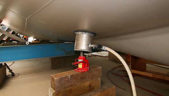
Here’s a Friday test for your powers of deduction. Can you tell the purpose of the device held in place by the hydraulic jack? It is a temporary system for getting water into the intake manifold for cooling the engine and generator.
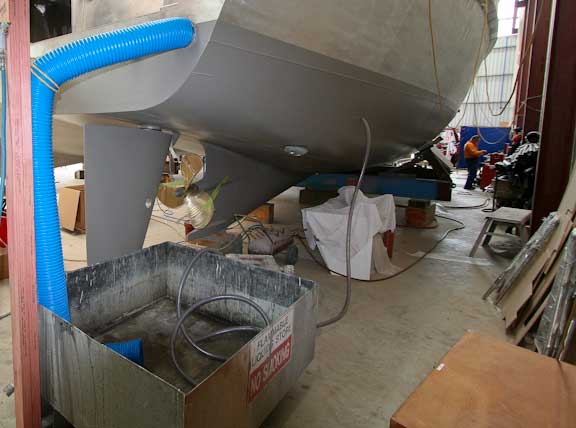
The other part of the temporary cooling circuit is this recirculating tank.
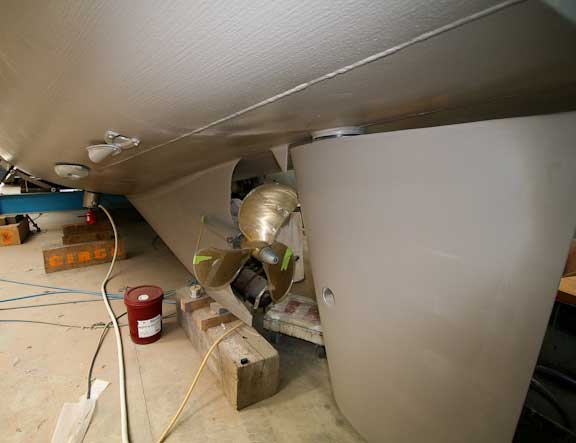
The propeller is now installed.The prop is 32″ (800mm) in diameter which puts the rudder size in perspective.
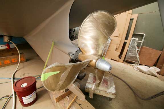
The choice of this prop design is the result of many weeks of noodling, computer runs, and dialog with experts. Contrary to what we wrote about overpropping Wind Horse, this prop is designed to allow full operating RPM. However, as the rated engine speed is 2300 RPM, we are in a comparable sweet spot for prop vibration as with the new wheels on Wind Horse.
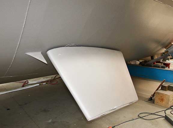
Stabilizers are now fitted. Note the welded weed deflector and the gap between it and the fin which is required for removal of the fin when it is pinned on center.
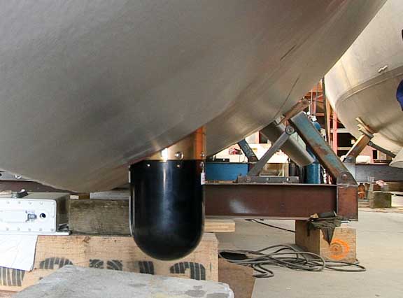
Does this look familiar? If you recall our blogs from March of 2007 this is the transducer for a Furuno CH270 searchlight sonar. The transducer retracts into the hull when it is not in use.
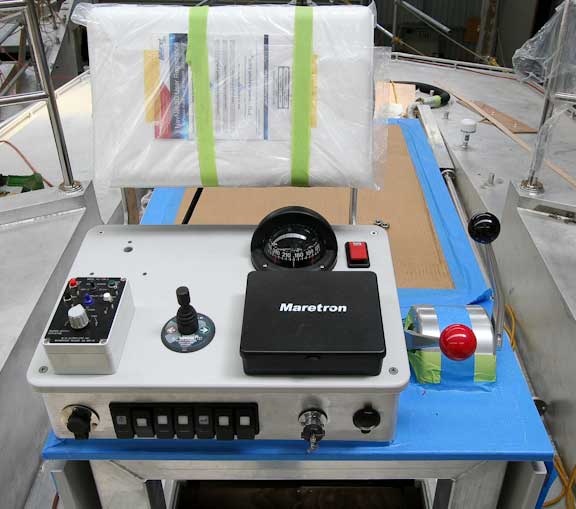
Last week we showed you the design for the flying bridge helm station. It now has most of its gear installed.
A Furuno Nav Net Three system is being installed on the first boat with a monitor at this helm and below.
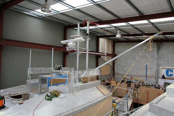
A last shot on deck before we see what is happening below decks. One of the booms has been installed to check running rigging.
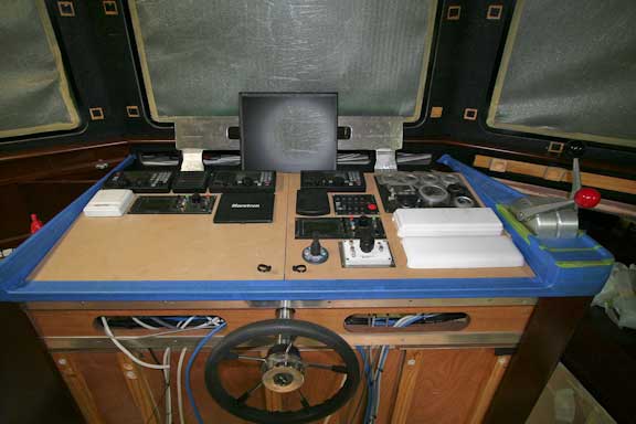
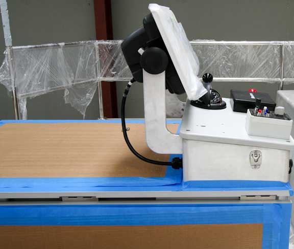
The interior helm now has its electronics in place. Note the clear space for the computer keyboard, mouse, and logbook. There will be three monitors.
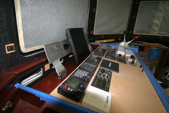
We are using a hinged support system as prototyped this fall on Wind Horse.
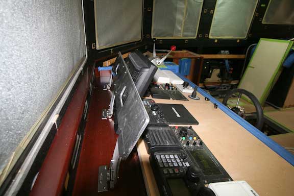
Hinging allows the monitors to tilt aft for access to cabling, and forward to optimize viewing angle when seated or standing.
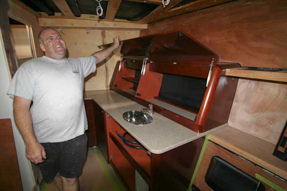
A final milestone. The last bit of joinerwork to be installed in the Owner’s suite. That’s Brendan, the head carpenter, proudly showing off the handiwork of Circa’s “chippies”.
Posted by Steve Dashew (December 11, 2009)
December 12th, 2009 at 8:21 pm
Hi Steve,
Whats your honest comments on the alloy work of CIRCA MARINE?
December 12th, 2009 at 8:48 pm
Circa’s metal work is the best we have ever seen, by a long way. Just look at the photos carefully.
December 15th, 2009 at 7:35 am
Steve,
had a few questions
I was wondering if you treated the area aft of the sonar tube the same way as directly aft of the bow thruster.
What is the horizontal measurement between the two masts?
What are the lengths of the bridge seats?
And finally. How can you stay away from NZ and not want to be there very day;)
She looks wonderful. I would love to see a picture or two of the aft cabin. I am sure it’s hard to photograph but it’s the one interior shot that has eluded your updates
Have a great holiday
Scott
ps. If one were to make the trek to NZ is there a good time on the horizon?
December 15th, 2009 at 7:00 pm
1-The transition on the sonar tube is different than the thruster as it penetrates the bottom of the hull.
2-The masts are roughly 13.1m/42.7 feet a part.For an antenna you would want to deduct a couple of feet (60cm) from this length.
3-Cockpit seats at inner edge are 2.8m/9 feet on the port side and the same to starboard if you count the scuttle top or 1.6m/5.25 feet if you don’t.
4-Office and sleeping cabins have been shown earlier, but not recently. We’ll reshoot the entire boat during sea trials early next year.
5-Todd Rickard is the best source of visiting info.
December 21st, 2009 at 10:45 pm
Steve,
Steve,
How have you addressed the apparent through hull of the sonar transducer and its mechanics? Is it enclosed in a coffer damn arrangement similar to the stabilizers?
I was just wondering as I had not seen this system addressed previously.
Kind regards and congratulations on being so close to launching hull #1! I am sure it will be a wonderful feeling.
Doug Haynes
December 22nd, 2009 at 12:09 am
Doug:
The sonar tube is a six inch (150mm) schedule 40 (1/4″ / 6mm) pipe contained within the forepeak which is isolated by two water tight bulkheads. The sonar tube flange is well above the waterline. Structural risks from the sonar are nominal.