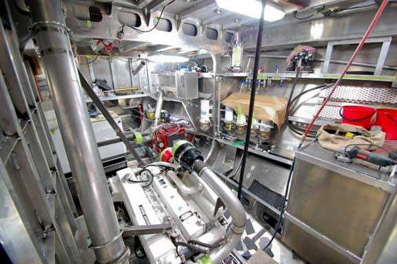
Let’s switch to the engine room; looking aft here from the vantage of the starboard forward corner. The as yet uninsulated engine exhaust is to the left and the work bench to the right.
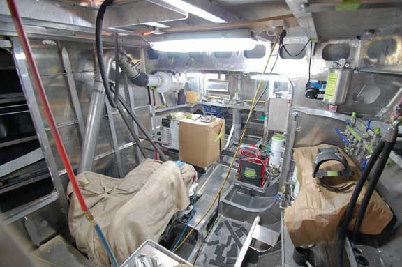
From the opposite forward corner. Most of the systems are covered to protect them, but this will give you a feel for the space. Engine is to the left under the tarp.
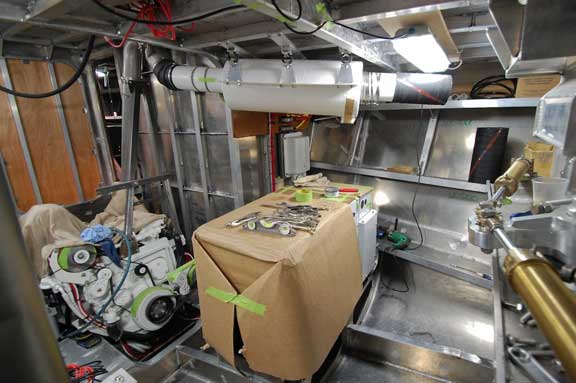
This from the aft port corner looking across the boat and forward. The steering cylinders are to the extreme right. The genset is under the cardboard, which has now been rotated 90-degrees from its previous position.
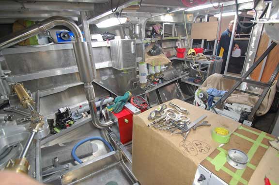
And a final overall engine room view, this time from the aft starboard corner. The genset is in the foreground. The red device centered is the Kabola diesel boiler.
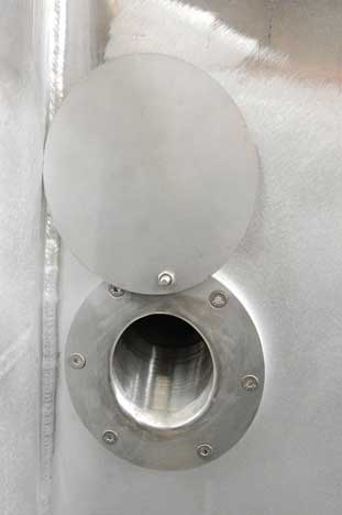
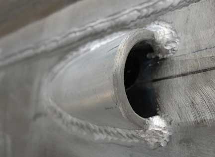
The Kabola exhausts through the forward vertical panel (inner transom if you will) of the swim step. The round cover is for use in heavy weather and in storage. We used this same approach on Beowulf and Kondor with good results.
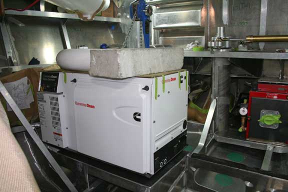
The genset, uncovered, in its new position. Lots of access all the way around inspection and maintenance. There is storage aft of the genset below hull stiffeners and under the swim step for lube oil inventory.
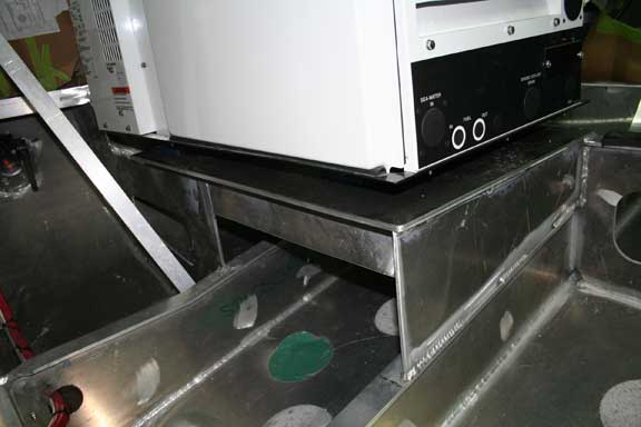
An example of why we love aluminum boats. Want a bracket? Weld it in place. Simple, strong, light. Need to change it, as we did with the genset? Get out the cut off wheels, plasma cutter, and grinder, and you are quickly ready to revise.
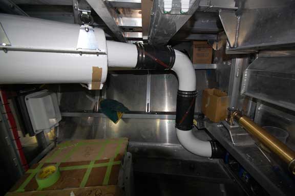
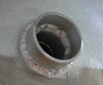
A few details on the propulsion engine exhaust system.
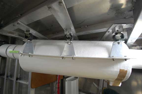
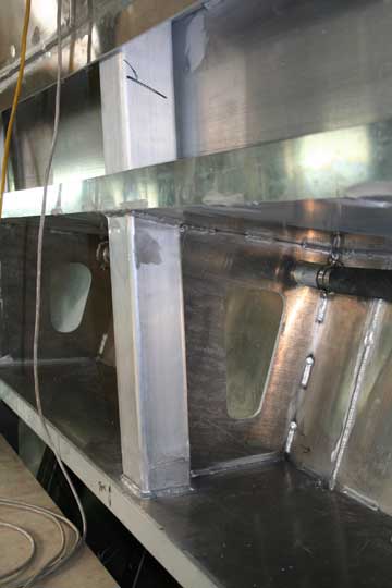
The first are the muffler isolation mounts. These eliminate noise transfer between muffler and structure. The taped block to the right under the end of the muffler will eventually be a drain. When the engine shuts down, any liquid left in the muffler is drained so the humidity within the exhaust system is kept to a minimum. This is simpler and less prone to problems than what has to be done with condensation in dry stack exhausts.
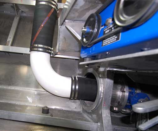
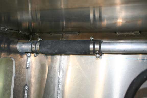
There are double T-clamps on all exhaust connections. Note the shut off valve and reinforced cut out in the frame (we have previously shown you details of these). One of the two autopilot pump sets is above right.
The basement fuel tanks vent through a common line into the day tank, which is then vented outside.
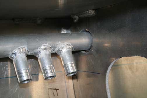
Manifold under the shear for three of the four basement tank air vents. The day tank acts as a settlement basin and allows any foam that accumulates during filling to compress so just air comes out of the vent. This approach reduces spill risks and allows for comparatively rapid fuel fill rates.
Best photo yet showing the house mullion and how it forms a bond beam between upper topside stiffener, deck, and top of coaming. The diesel vent can be seen middle right, under the shear.
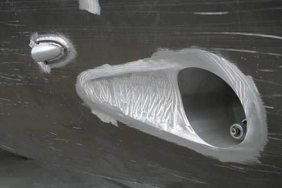
The thruster is installed, ready for is prop. The external cover to the left is for the forward black water tank exhaust.
Detail of a topside through hull cover plate. This creates a negative pressure area over the exhaust when the boat is underway.
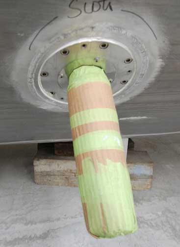
The NAIAD stabilizer actuator mechanisms are now installed. Eventually the fins will be fit over these shafts. The mechanisms reside in water tight coffer dams.
A final photo from this exhausting update. Genset exhaust outlet through the transom.
Posted by Steve Dashew (May 26, 2009)
May 28th, 2009 at 8:19 am
I’ve been enjoying the FPB updates. I’ve a question concerning your not using a traditional steering wheel. Having owned a vessel that had it’s autopilot computer, among other things, crisped by an “near” lightning strike, what do you think the lightning issues are with regard to your steering approach?
Thanks!
Sincerely,
Roger A. Arrowood
May 29th, 2009 at 10:36 am
Roger:
Lightning is always in the back of our minds. We have a degree of protection from the metal hull acting as a Faraday cage. On Wind Horse, when in lightning risk areas, we disconnect the lazy pilot cables. We also have the ability to steer with the engines if the rudders are centered. And of course, there is an emergency tiller and relieving tackles.
The FPB 64 has a hydraulic manual helm pump, in addition to the two pilot systems and emergency tiller (with single engine we felt this was a requirement).
June 2nd, 2009 at 1:03 am
Thank you for this very informative Website.
Having decided that a narrow stern and balanced fore and aft ends were the way to go to minimize drag from the wake, among other advantages, why not go all the way and design a pointed canoe stern, which would provide even less drag/wake and work well with the single engine power solution?…
The advantage of the stern boarding platform could be preserved, as a small cockpit with one or two swing out doors to fully enclose it could be easily designed, making boarding of unwanted guests a lot more challenging…
June 3rd, 2009 at 8:23 am
Good question Frank:
The answer to this is not easy. Canoe sterns have some advantages at slower speeds, and in certain sea states. But they also have some disadvantages in terms of internal volume, deck space, dinghy storage, and water flow at higher speeds. The heavier and slower the boat, the better off they are compared to transom sterns. Heavier boats also have deeper props, so these won’t suffer cavitation in big seas as badly as would be the case with a lighter configuration done with a canoe stern.
Note that with a sailboat canoe sterns rarely make sense because of the hit on upright stability.
We have been observing the Norwegian double enders, power and sail, and will write up some more on this subject with photos in the next few weeks.