
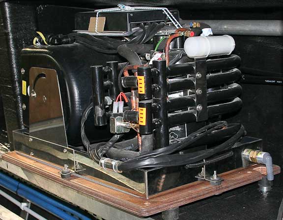
Most motor yachts these days use household fridges and freezers. This has substantial cost advantages, but brings with it enormous power consumption. We have stayed with our highly efficient specially insulated box design, and these 24 volt DC Danfoss compressors connected to evaporator plates. There are three independent systems, each capable of being used as fridge or freezer. The combination of this hardware and our box design has proven to be the most efficient system we have ever used.
The compressors are cooled in the same fresh water tank that is used for the air conditioning system (discussed in the previous post). This is accomplished with a passive “keel coolers” mounted through the top of this cooling tank. We first tested this approach on Beowulf 14 years ago and it works so well that the compressors receive sufficient cooling even when the boat is hauled out for storage.
There are four air conditioning units, each with its own cooling circuit. These self priming pumps circulate fresh water from the cooling tank through the condensing coil on the air conditioner. Eliminating salt water from the air conditioning system and using individual pumps has many advantages:
- Eliminates risk of a major flood that comes with pumping salt water through the boat.
- Better pump life.
- Longer condenser life on air conditioners.
- Eliminates problem prone (and complex) relay controls.
- Easier pump replacement if required.
- You can leave the air conditioning running when away from the boat without undue worry.
- More efficient in terms of power consumption.
Although the Climma air conditioners are exceptionally quiet, the pallets are still mounted on rubber grommets, so any noise or vibration is isolated from the surrounding structure.
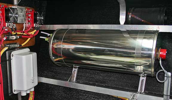
Running under the upper topside stiffener in the engine room (starboard side aft) is the domestic water heater. This has a dual heat exchangers plumbed in series with the diesel boiler, as well as two electric heating elements for use when on shore power and to add load to the genset if required.
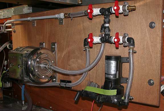
The fresh water pressure system is coming together. There are two pressure pumps, one drawing from the forward tank and the other from aft. This gives us an easy way to change trim or draw from a different tank without messing about with valves. There is the benefit of built in redundancy as well.
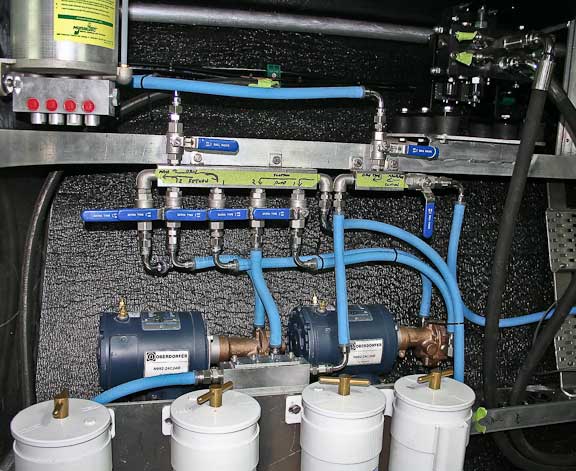
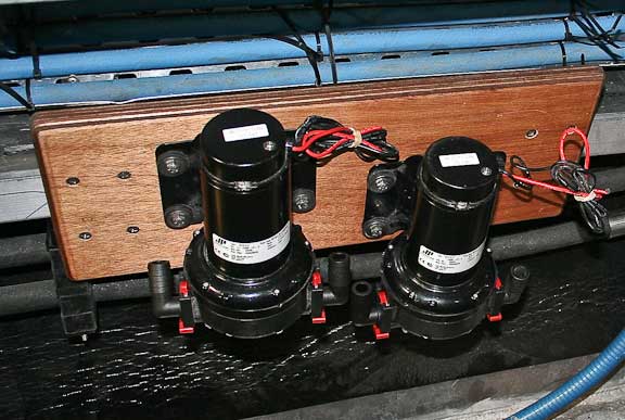
The fuel transfer system is now almost completed. Note that the covers over the motor brushes (aft end of pumps) are accessible. Although we have yet to have any maintenance issues with these pumps on Wind Horse we want to make the eventual changing of brushes as painless as possible. The system is wired and plumbed so one of the two pumps is in use when transferring or polishing fuel. The other is a spare, ready to go with the turn of two valves and a selector switch.
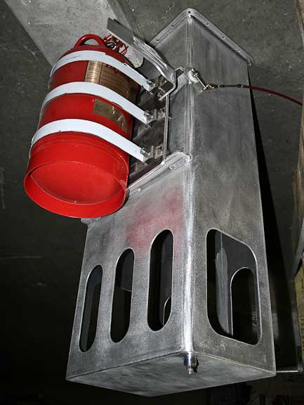
You are looking here at the engine room air intake. The flange at the top of the weldment bolts to the underside of the deck. The red canister is the fire suppression system. Note the Morse cable and bell crank arm towards the top. This is connected to an interior closure plate, which is used to seal the engine room in storage, during a fire, or if disabled in heavy weather.
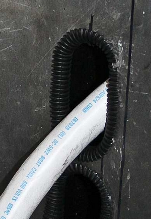
Where plumbing and wiring penetrate structure the edges of the cut outs are chafe protected as shown here.
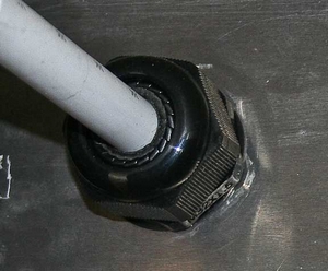
Water tight bulkheads require glands to both chafe protect and maintain the integrity of the bulkhead.
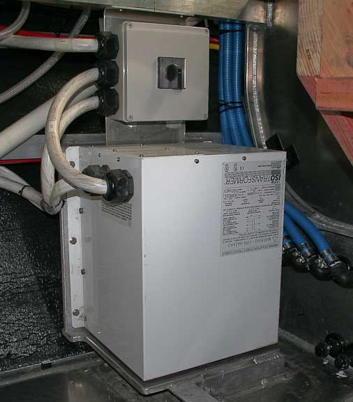
A final system photo for this update, the isolation transformer. This reduces the risks arising from grounding problems with shore power. There is also a center tap to allow 115VAC shore power to be stepped up to 230.
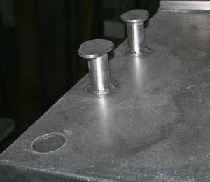
OK, let’s move outside. The socket in the lower left corner is for future use with a two-inch pipe. It could be used with a wind generator or solar array framework. The stern bollards (for dock lines) are shown in the center of the photo.
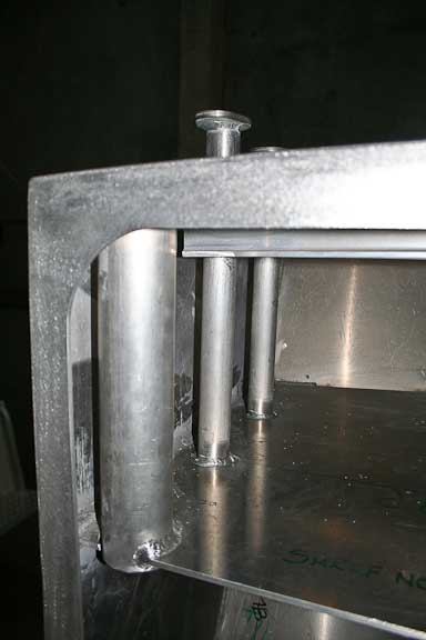
Looking inside the swim step locker, aft side. Note how the two inch pipe socket and bollards actually extend down to the center locker shelf, creating a bond beam for strength.
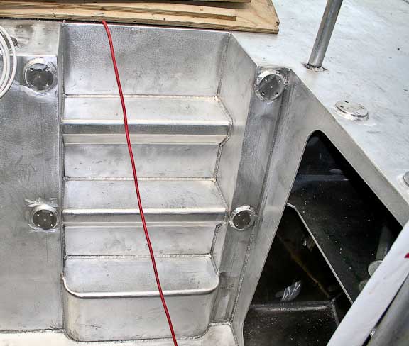
The four tapped pads either side of the stairs down to the swim step are for affixing handrails. The tapped holes do not penetrate the transom. No holes equals no leaks.
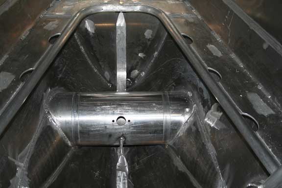
A good shot of the second FPB 64 bow thruster tube.
Posted by Steve Dashew (June 26, 2009)
June 28th, 2009 at 6:49 pm
I’m enjoying the build of the 64 as much as I enjoyed the build of Wind Horse. I wish i’d saved each update, it was an amazing story to follow.
I now wait with anticipation for each travel update, this is fantastic reading.
Thankyou Linda and Steve for taking us with you.
Cheers
Scott
p.s. watch out for the Bundy Bear!