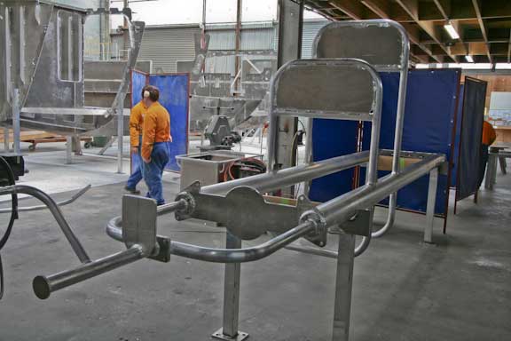
You are looking at what will eventually become the mast assembly on the FPB 64.This is a complex engineering job, with many tradeoffs and conflicts. As such this has taken a substantial amount of Circa’s and our time. Like many yacht details, there is more cost involved in the design than the actual fabrication.
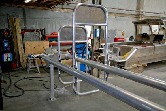
The mast assembly does many things:
- Provides a base to which the booms attach.
- Is part of the get home sail plan.
- Hinges for storage, bridge clearance, and maintenance.
- Is integral in the flying bridge awning system.
- Provides for navigation light bases, anchor light, and aft deck lights.
It is also the focal point for electronics antenna including:
- Two radars.
- Satcom.
- Six whip antennas
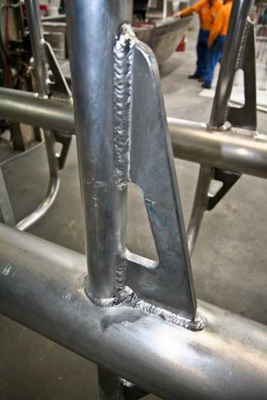
The radar platforms are cantilevered and subject to reverse cycle loading from motion, so care has to be taken with the welds. These are gusseted, as shown above, to spread the load.
Systems are now well along their installation time line. Note the orderly fashion in which the plumbing and wiring are installed.
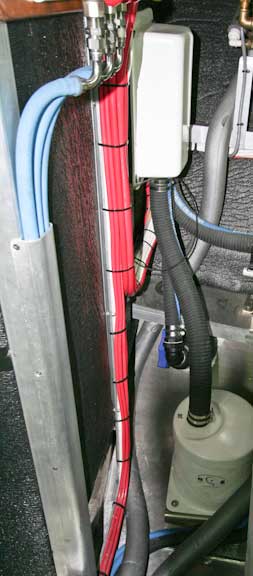
Here is another example of a tidy installation. The blue hose is between oil sumps and the oil changing pump.
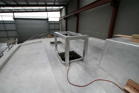
Looking above at FPB64 #2, the flying bridge table (another major design project!) is now welded.
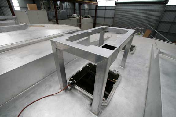
This will eventually have hinged table wings, engine controls, and electronics.
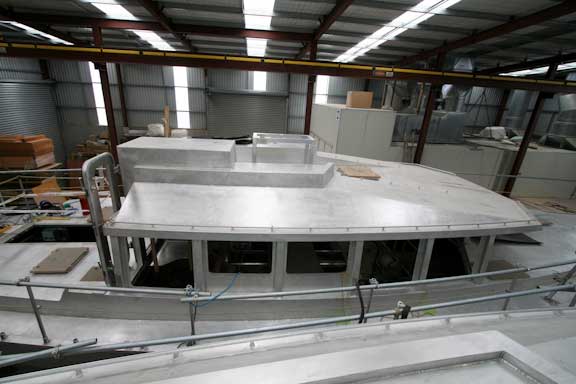
We are looking here from the aft port corner of the flying bridge towards the bow, with the entry “scuttle” to starboard.
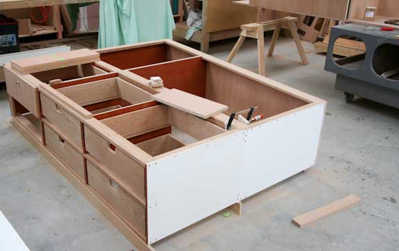
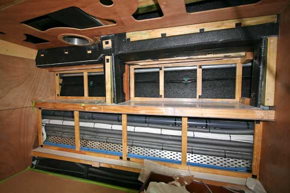
Furniture is now underway for the second FPB 64. The bunk for the forward cabin is shown above.
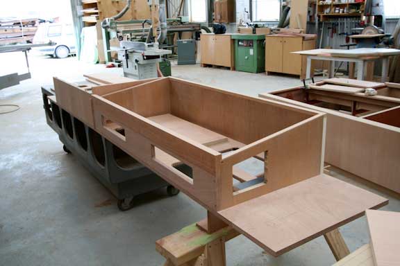
And a start on the navigation deck for the second boat here. The angled portion and segment to its right, defined by the forward window, is four feet (1.2m) long.
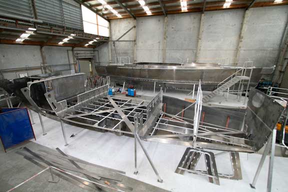
FPB 64 hulls three and four are coming along. The backbone of four, with its closely spaced girders for strength and to constrain movement of fuel and water, is clearly shown. The tight baffling of the large tanks reduces sloshing noise, and helps with motion at sea.
Posted by Steve Dashew (October 9, 2009)
October 11th, 2009 at 6:43 am
Steve,
I noticed that there are no pressure release “flaps” above the forward windows. Have you determined that these won’t be needed becasue of hull design?
thanks
Scott
October 11th, 2009 at 5:34 pm
once again,
I am in awe of the build quality and the thought process behind the detail.
The masts on boats I have worked on have not had to do the loads that will be asked of this design, and yet they have failed at different times and places.
Obviously, your team wasn’t involed.
GREAT work, really good to see this level of craftsmanship.
Thankyou for sharing the process with us.
October 13th, 2009 at 8:44 am
Steve-
The gussets on mast projections appear to be on the under side of the projection. Since the significant loading will be downward, would it not be stronger to have the gusset plate be above the projection, in tension, rather than suppporting a compression load?
October 13th, 2009 at 9:41 am
Hi Bill:
Generally speaking we try to avoid welds in tension where possible. Shear is best, followed by compression. In this case, the loads are so low compared to the parent metal and weld area that the position of the gussets makes little difference.