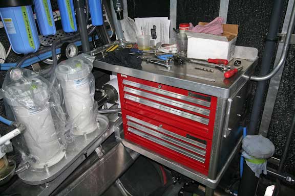
Here is a photo to start your heart racing! A double set of tool drawers under the work bench. This feature has been on our wish list for years, but for various reasons we have never been able to make it work. Aside from the space these drawers consume, access to a variety of systems has to be maintained.Tool drawers are a standard feature on the FPB 64.
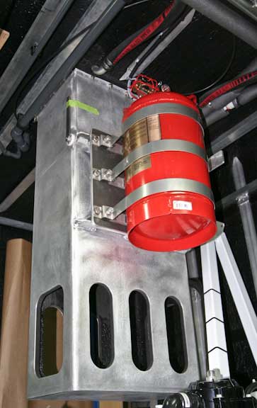
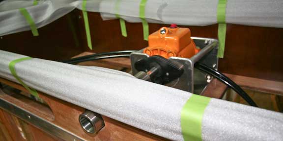
We keel showing you photos of the air intake system in the engine room, now with the fire suppression system mounted. The fire suppression system is triggered automatically or manually with a Morse cable. It is tied into an automatic shut down for the engine, genset, and diesel boiler.
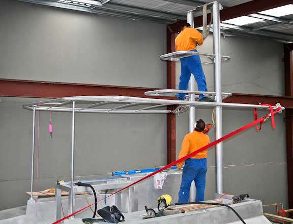
The two men in this photo will give a feel for the scale of the mast array, flying bridge, and awning frame.
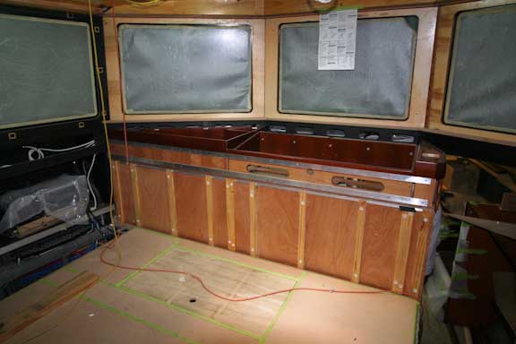
The nav desk at the forward end of the great room is coming together.
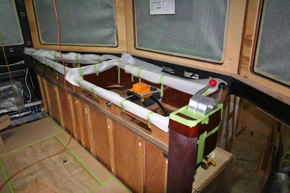
Engine controls are now mounted.
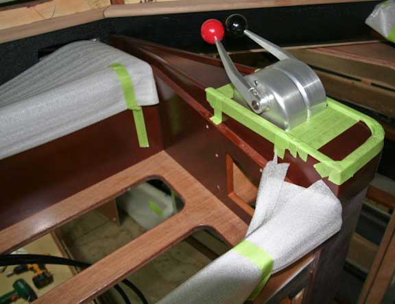
We are using Hynautics hydraulic controls for shift and throttle. These are considerably more difficult to install and few yachts use them these days (they market to commercial users). However, for single engine systems their reliability is worth the extra cost.
That is the helm pump (orange) above. This is intended as a manual back up to the electronic steering system. The steering wheel is designed to be easily installed or removed.
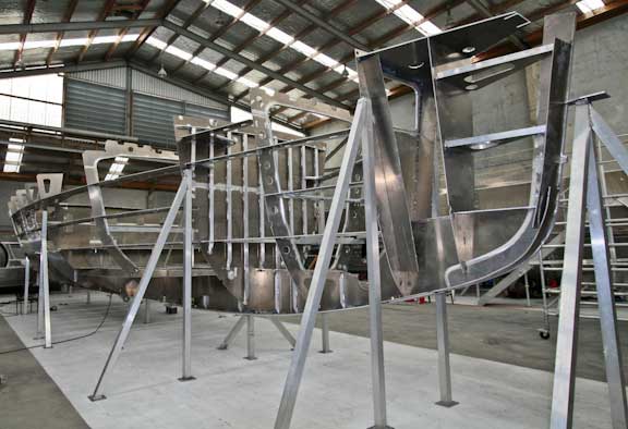
We’ll finish with a few details of hulls three and four. Previously we discussed the 40mm thick stem bar, which you can see in this side view of the hull for number four. It is not only massively thick, but deep as well. Note the three horizontal frames to reinforce the stem bar. The bulkhead directly aft of the stem, to which the frames are attached, forms a watertight compartment.
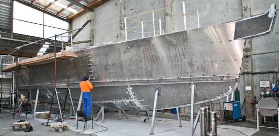
Hull number three, above and below, is now fully plated.
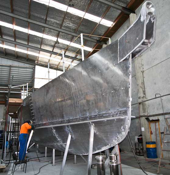
Note the knuckle at the cutwater. This is designed to help the bow ride over debris and ice.
Posted by Steve Dashew (November 4, 2009)
November 4th, 2009 at 4:10 pm
How does the mast and awning support breakdown/fold for bridge clearance and storage?
November 5th, 2009 at 10:24 am
Hi Skip:
The mast is hinged at its base, right at the eyebrow which surrounds the house structure. There will be an A-frame attached to the table to control the descent or raising of the mast. The awning frame will unbolt from its vertical support and the attachment to the spreaders.
November 4th, 2009 at 5:24 pm
Hi Steve:
On the mast, will the upper radar support frame swing a 6 foot open array? If not, how will this reduce the horizon of the big radar by mounting it lower by a few feet?
LOVE the tool box! I assume the white canisters to the left are part of the water maker system?
Weren’t some of the Murphy gauges also mounted on the engine room air intake so they were visible from the engine room door?
I would never have thought of the cutwater detail – and would have designed a gentle curve in from the knuckle to the keel. Thats the kind of stuff that hundreds of thousands of miles at sea teach you.
Best regards
Pete
November 5th, 2009 at 10:21 am
Hi Pete:
There are two platforms for radars on the mast. The lower is engineered for a commercial grade system (heavy) like the Furuno 2117 on Wind Horse. The upper platform has room to fit a four foot (1.2m) open array as backup. The difference in height will make no discernible difference in long distance range. However, for close in work with small targets like lobster buoys lower is always better (too high and you miss the close targets).
The large white filters to the left of the work bench are the pre-filters for the watermaker (commercial grade).
All the Murphy gauges are located where they can be seen from the engine room door, on the forward side of the air intake.
November 5th, 2009 at 8:53 am
Steve,
The flared extrusion running along the water line, I didn’t see this on hull 1 when it came out of the shed. Is this custom to this hull? and what exactly will it do? seemes like it will work hard constantly as the boat goes through a sea of any size and I woudl think it would work against the boyancy when going down hill and poking into a wave?
thanks
Scott
November 5th, 2009 at 10:05 am
Howdy Scott:
I think what you are referring to is a temporary plate for fairing the hull, which is later removed. There is also slight transition above the waterline in the hull shape. There are many positives to this in terms of the shape we want to present to the water in normal weather and in extreme conditions. Like most things with boats, there are also some negatives. However, the bottom line is that it improves performance.