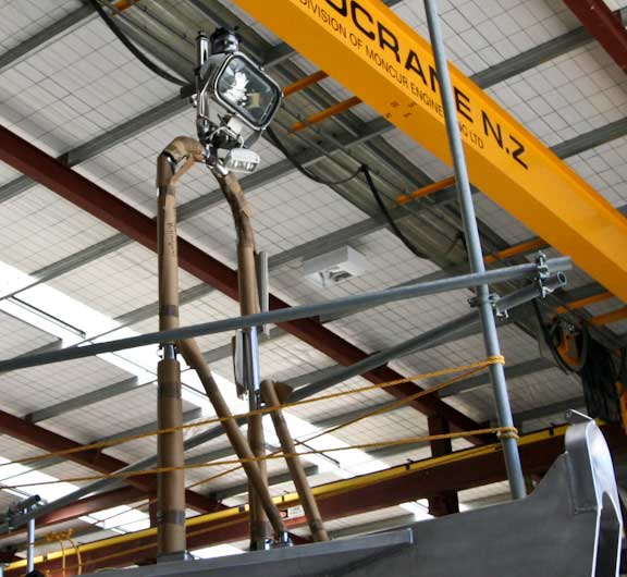
One of the more difficult design areas on the FPBs has been the forward “mast”. It does a number of jobs, some of which conflict with each other and/or different requirements. We’ve been fiddling with this on the FPB prototype Wind Horse since launching. What you see here is the result of that thinking and experience.
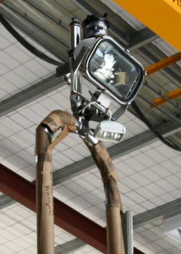
The forward mast serves as a base for the forward anchor light (we have another on the aft mast), the foredeck flood light (bottom angled down), the large spot light, forward range light, horn, and Windex. It is also the forward end of the single side band radio long wire antenna, and plays a part in the emergency sailing rig.
The most difficult chore is providing a location for the big spotlight which allows illumination of the water close to the bow without reflecting off the deck or anchor.
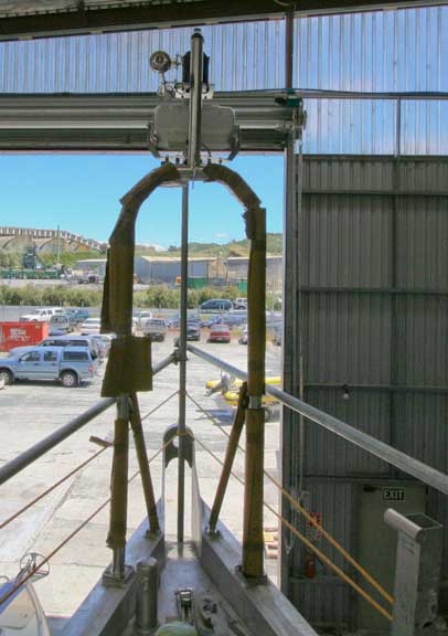
Then there is the view, or lack thereof from the helm. Wind Horse has great sight lines, but we have found the bulk of the six inch (150mm) single mast annoying (we are switching to this newer, more open design).
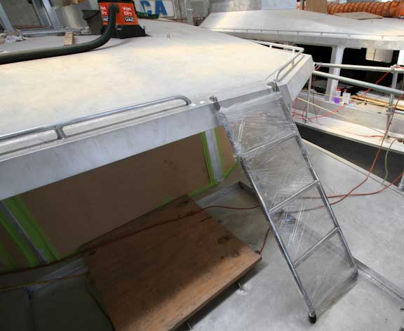
Another small, but important detail which has taken a lot of engineering time. This ladder sees occasional use. When not required it would be better to have it out of the way.
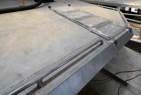
On the FPB 64 this folds back, onto the house.
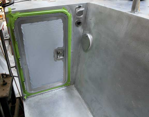
The doors for the swim step lockers are now in place.
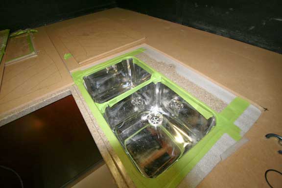
Countertops are being installed, the next to the last joinerwork detail.
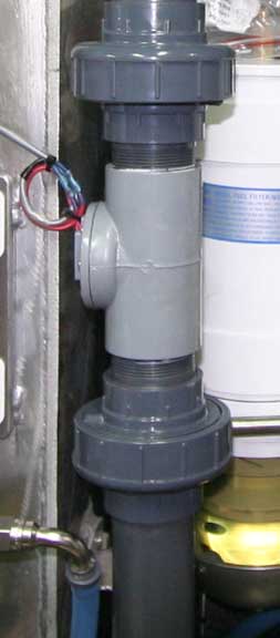
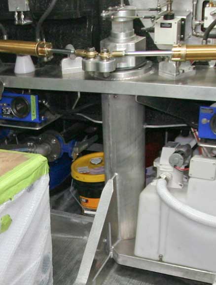
Speaking of details, the light gray device is a flow sensor in the output line of the damage control pump. One of these is also on the inlet of the main engine raw water pump. These flow sensors are connected to the NMEA 2000 system and give an early warning of problems.
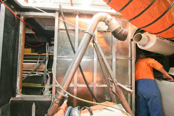
We’re in the engine room of the second boat now. This is a clear photo of the bracing system on the dry exhaust riser on the main engine. It is designed to be supported off the engine and isolated from structure to minimize noise transfer.
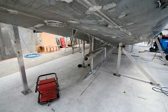
Plating is complete on hull number three. This is a good view of the slight tunnel in the aft sections of the hull. Circa’s crew have done an amazing job at bending 12mm (15/32″) plate to this shape.
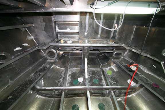
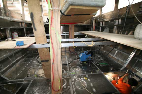
This photo (also hull #3) gives us a chance to take in the aft end of the engine room before it fills with equipment.
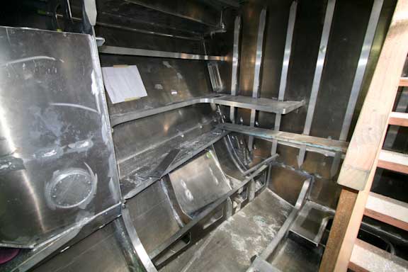
The forward end, port side, of the engine room. Note the continuation of the middle topside stiffener into the work bench on the bulkhead.
Meanwhile on the inside of three the tanks are being tested. The red and clear hose device is called a manometer. This is a highly accurate indicator of pressure. Tiny leaks will result in a pressure drop which shows up on the manometer.
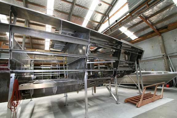
Hull number four is now fully framed and plating is starting.
Back to the engine room on number one. Note the yellow 20 liter (five gallon) pail of oil. There is a second behind this. More room for oil storage exists between the transverse frame shown and the genset (white box on the left).
Posted by Steve Dashew (December 18, 2009)
December 18th, 2009 at 2:13 pm
Steve,
1) Why did you leave out “relief pannels” from the “eyebrow”? Does the hull shape shed more water to the side?
2) are the flow meter impleller activated? if yes what about barnacle growth on intake? if not what is it?
December 18th, 2009 at 2:26 pm
Two reasons for leaving out the relief panels. First, they have only opened twice in 45,000 miles on Wind Horse (she is very dry going uphill). Second, the FPB 64 should have less water on deck than the 83 as a result of her shorter length relative to wave period.
The raw water alarms have a vane. Growth in the raw water line has not been a problem so far (four+ years) with Wind Horse (probably due to the lack of sunlight).
December 18th, 2009 at 5:13 pm
The vessels are looking great, congrats!…
Coming back to the dry stack/keel cooling versus wet exhaust/seawater cooling argument, I fail to see why the best features of both systems cannot be combined into a hybrid wet exhaust/keel cooling design…
With aluminium as the hull material and various tanks already designed as heat exchangers between sea temperature and fresh water to be cooled, keel cooling should present no technical difficulty: in fact, the keel should be just about perfect for this purpose. The raw water pump with inline flow sensor can then be used to inject water in the exhaust just past the riser to cool exhaust gases down and muffle the noise.
The raw water could even be injected into the water jacketed riser to keep it cooler, even though there would be added weight to be supported by the frames bolted on the engine.
Keel cooling would bring added peace of mind, which is an essential ingredient of happy cruising…
December 19th, 2009 at 10:33 am
Frank:
We considered in detail exactly the scenario you are describing. But when you do the calcs for the tropics and 90F water, a huge amount of painted surface area is required for engine cooling all of which has to be channeled. Or you can go to exposed tubes which are not damage tolerant enough for our service.
The bottom line is we have not had a problem with direct salt water cooling on Wind Horse, Beowulf, Sundeer, or either of our Intermezzos in more than 250,000 miles of cruising, some of which was in debris filled areas. This experience tends to color our approach when we consider the risks associated with exposed keel coolers.
December 19th, 2009 at 10:38 am
Howdy Pete:
We have these same sensors on Wind Horse. The starboard engine sensor does occasionally get stuck. While it is easy to remove the top, a light tap with a long handled screwdriver is all it takes to free it. The vendors tell us this very occasional problem is because we used an oversized sensor. We have correct sizes on the FPB 64.
The NMEA 2000 system and Maretron display allows for different event reactions to be programmed. We do not use these devices for auto shut down, just as an early warning. With the crash pump any time the pump starts or gets close to the end of its cycle the alarm will go off.
December 18th, 2009 at 5:26 pm
Hi Steve
The flow sensors are a great idea but a few caveats from experience with them in a different application.
We used vane/paddle type flow sensors in the riser of a sprinkler system for a building. Over time, we found that they would occasionally get stuck in one position or the other (alarm/normal). In our case, it was a frustrating exercise to try and unstick them because of their poor design.
To that end, I hope that your system is more user friendly to fix, that an errant alarm condition can be silenced or bypassed at the helm, and that the alarm is just an alarm and doesn’t prevent the engine from starting or worse – shut it down.
Regards
Pete
December 18th, 2009 at 9:12 pm
Steve,
Is the flow sensor a meter or a switch? I am guessing it’s a switch indicating flow or no flow, which is fed to the Maretron Switch Interface Module (SIM100) where it’s converted to an NMEA 2000 signal.
With regards to the picture showing the work bench, is that a tank on the side of the hull with an oval shaped clean out access port?
Wow, hull #4, I didn’t know so many were under construction. I hope you have continued success!
December 19th, 2009 at 10:40 am
Rich:
There is an inline paddle (spring tensioned) which operates a microswitch. You have the rest of the NMEA system correctly scoped.
January 4th, 2010 at 10:15 pm
Hi Steve,
Thanks for all of your work in documenting these builds and your blogging.
I see you have used the same floodlight that you have on Wind Horse.
These are certainly 1st class fixtures, but I am wondering if you considered any of the new High Intensity LED lights on the market. There are some very high quality lights that now have performance of some high wattage AC bulbs with a much longer lifespan, so the likelihood of a bulb failure at an inopportune moment is greatly reduced.