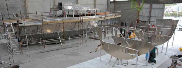
Our apologies for being so late with this update. The many requirements of boat building has been keeping us busy. So, there are lots of photos to review (the newest of which is now three weeks old), starting with the one above. The house is now in situ on FPB64 #1 and construction of hull #2 has begun.
We’re pleased with the way the aesthetics are turning out – maintaining the family resemblance to the FPB prototype Wind Horse.
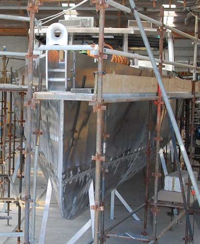
We would love to have a clean photo bow on to show you, but that won’t happen until the boat is completed and moved outside.
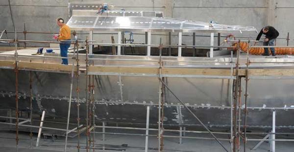
Looking forward here, at the foredeck and forward half of the flying bridge.
Then the aft section of the flying bridge towards the aft deck.

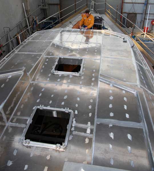
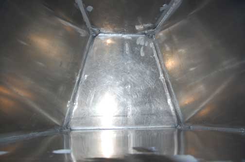
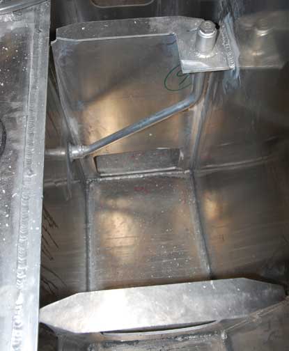
Looking down into the anchor chain bin at the forward end of the forepeak. There will eventually be drains at the bottom, so sea water coming below down the chain pipes self bails.
Forepeak finished, ready for systems installation.
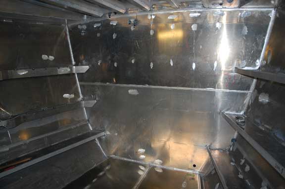
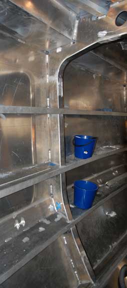
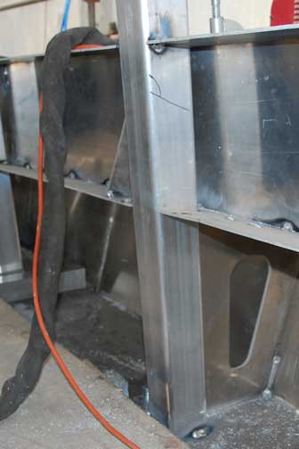
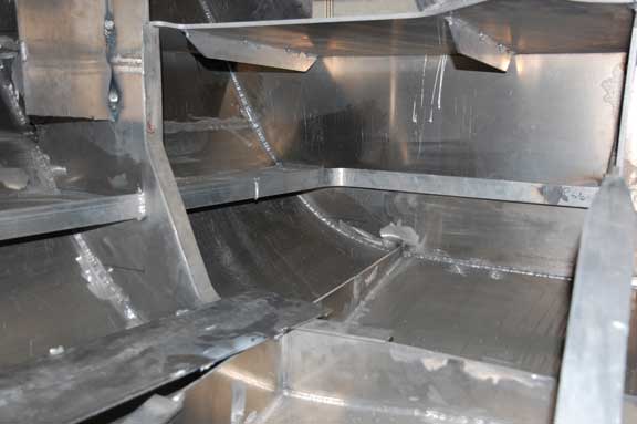
Aft end of forepeak. Note the topside stiffeners with their cut outs and roundbar flanges. These will eventually be incorporated into a storage system for the varied (and large) amount of equipment that will be stored here.
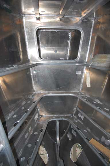
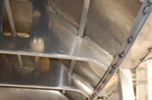
Opposite side of the forepeak watertight bulkhead, the forward end of the Owner’s suite above. The massive topside stiffeners, which run the length of the hull, are incorporated into the interior design. The aluminum surface at the bottom is the top of the forward fresh water tank.
There is a web frame in the middle of the forward cabin, to break up the span. This is the part of the hull that feels the highest dynamic loading when fighting through storm force headseas – and no place to skimp on structural factors of safety.
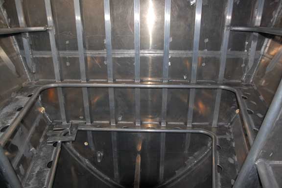
Intersection of the intermediate frame and fresh water tank. It continues through the tank. Note the margin plate which makes the connection between tank top and bottom plate. This provides local stiffening in the 12mm bottom plate, forms a channel in which condensate or leaks can be collected, and is simple to weld.
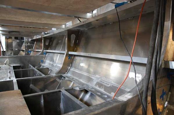
Looking aft, from the forward end of the basement (under the great room). The partial height bulkhead in the background is the aft end of the great room. Fuel tank tops are not yet installed.
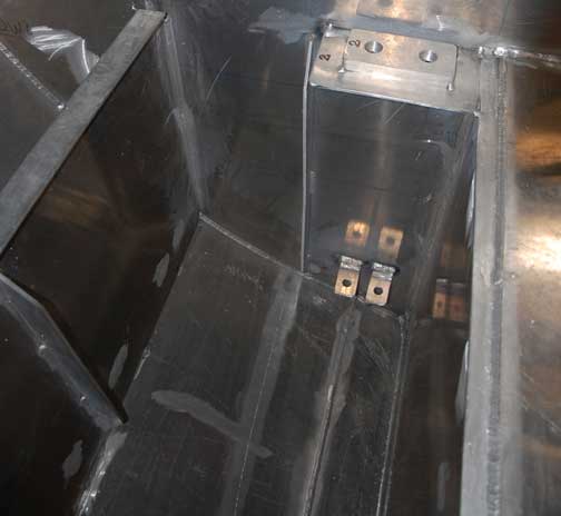
A detail inside one of the fuel tanks. The fittings top center will eventually be incorporated into the fuel plumbing system.
The pipe is the fresh water pick up.
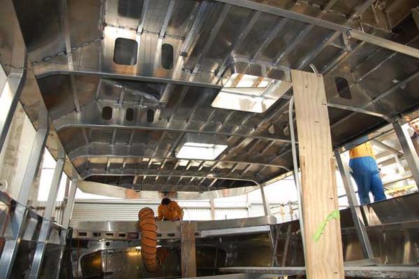
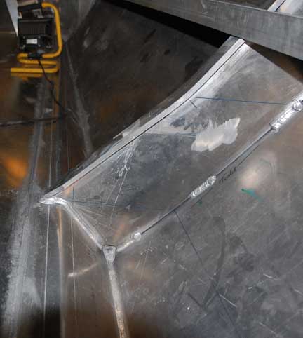
The great room roof structure and window mullions potentially has to carry massive loads in a severe storm – hence the substantial amount of welded structure.
Close up of the roof panel to “eyebrow” intersection above.
The twelve side window mullions – one of which is shown above – are supported at the top of the welded coaming, the deck level, and terminate at the upper topside stiffener. The “reaction” of the load between the topside stiffening beam and coaming weldment creates what is known as a “bond beam”. This is a very stiff, strong, and efficient structure. The twelve side mullions are then forced to work together by the stiffness of the roof structure, which distributes any bending loads from side impact throughout the mullions.
Finishing up inside, this is a look under the swim step. This area will house some systems, a lot of plumbing (genset, engine, toilet, bilge pump exhausts), with space left over for engine room liquid bulk storage (lube oil, hydraulic oil, steering system oil, control system liquid, fuel treatment chemicals, outboard oil).
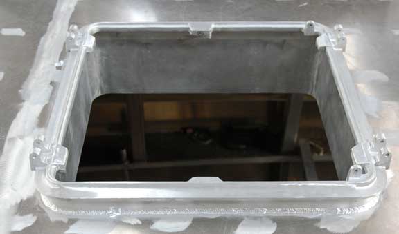
And now a few details. This is a typical hatch coaming. The overhanging lip formed by the cast hatch base is used to secure a hatch storm cover.
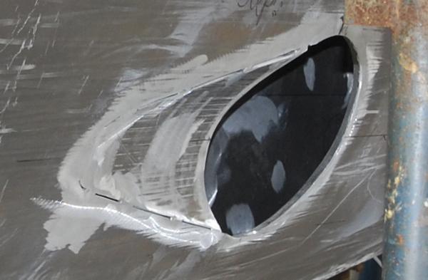
Fairing on the bow thruster topside penetration, tacked in place and ready for final welding.
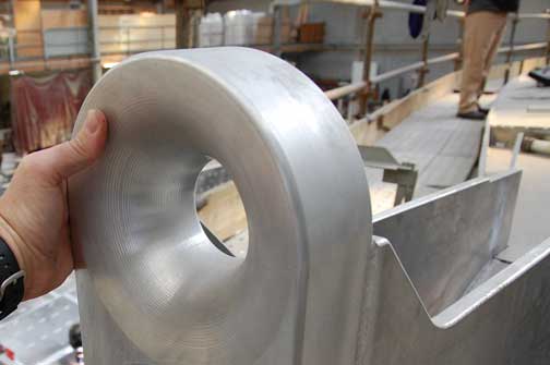
Close up of the bow fairlead. This is mostly used for a chain snubber, but also sees duty with bow lines and bow springs under certain conditions. Its worst case scenario is for hanging onto a parachute anchor, or for towing.
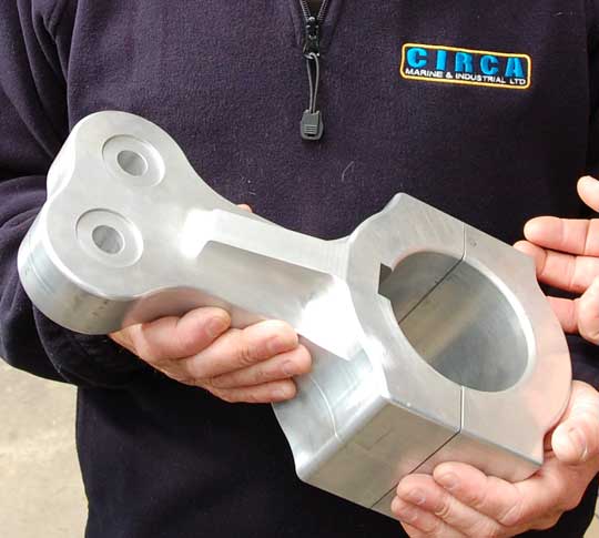
The tiller which goes onto the rudder shaft, and to which the hydraulic cylinders are attached. This is machined from a solid piece of aluminum. No welds or stress concentrations here.
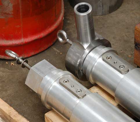
Rudder shafts for the first two boats. The hex machined onto the top is for the emergency tiller connection, shown top right. Just below this is the clamping area for the tiller. All of this work, the CNC machining of the tiller in the previous photo, and these rudder shafts, is done in house at Circa.
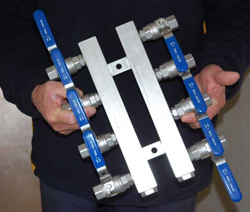
Finally, systems work is starting. This is the stainless fuel tank selection manifold.
Posted by Steve Dashew (December 1, 2008)