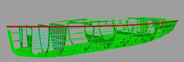
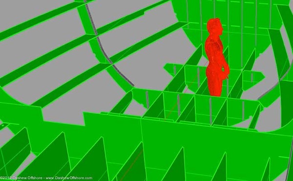
We were working through some design issues last week using a new (beta) version of Rhino 3D, and thought that a quick set of graphics on the FPB 64 structural grid might be of interest. These may help put the construction photos we show into context.
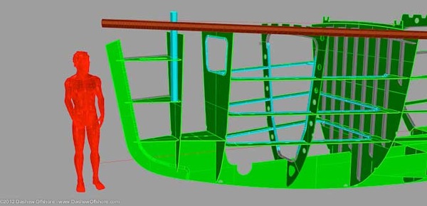
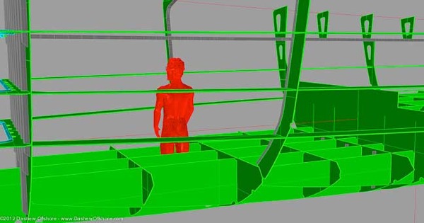
The structure in the bow is built with collision in mind (the model is 1.85m/six feet tall).
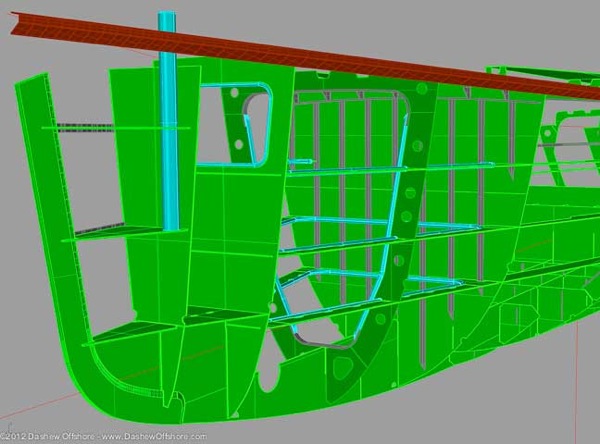
The stem bar is not only massively strong on its own, but it is reinforced by three horizontal web frames.
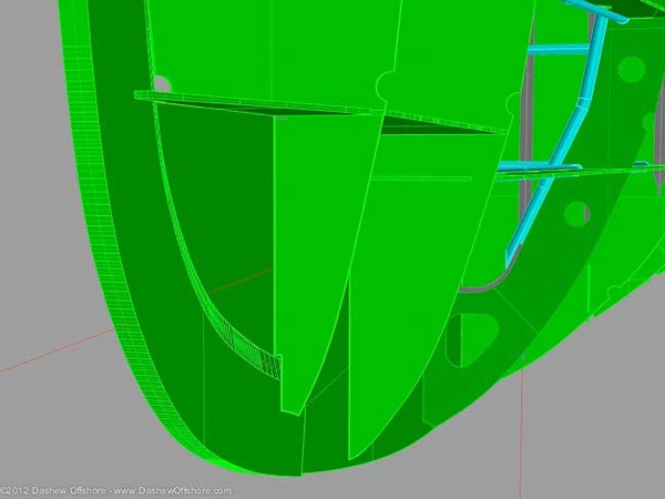
The stem bar is 40mm thick, further reinforced by the topside plate, 12mm here, for a total thickness of 64mm (2 5/8″).
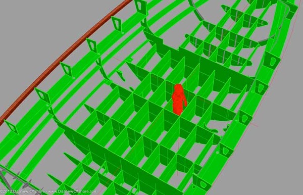
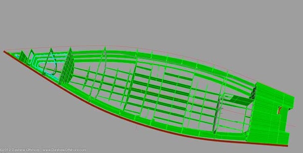
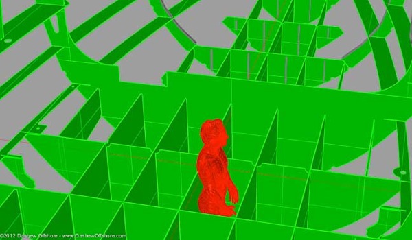
The bottom of the hull is stiffened by a series of deep longitudinal girders and transverse frames. These work as baffles for the fuel and water tanks, minimizing noise from sloshing and the dangerous impact of free liquid effect in heavy going.
One of the many advantages of aluminum construction is the ability to have integral tanks. The fuel tanks, centralized for minimum impact on trim as fuel levels change, are over a meter (three feet) deep.
Fresh water tanks are on either side of the fuel tanks, separated by coffer dams (empty sections).
Integral tanks form what is in effect a double bottom, reducing the risk from a hull puncture, unlikely though that is given these scantlings.
Posted by Steve Dashew (January 14, 2012)
January 15th, 2012 at 9:14 am
The 3 web frames supporting the stem bar are usually called “breast hooks”.
With your double bottom tanks, it looks like that tanks cannot be entered for inspection. Or perhaps you aren’t showing cutouts for access so somebody can crawl around inside the spaces. Actually how do you weld the tank top on – plug welds everywhere or 100’s of manholes that we cannot see?
January 16th, 2012 at 1:55 am
Hi Evan:
There is a trade off between inspection access with more widely spaced frames and longitudinals, the noise and motion of liquids, unsupported spans, and access. Years ago we came to the conclusion that the boats were stronger and safer in heavy weather with the closer spacing. With a steel tank you would not be able to take this approach. In the last 30 years we have had no experience that would indicate a different approach was warranted. There is an inspection port over each tank sump, and should it ever be needed, more could be added.
Aside from the construction material, another factor is the use of a day tank(s) so we never return hot fuel – and its attendant problems – to the main tanks.
January 27th, 2012 at 12:46 am
Hi Steve,
I really think that not only the day tank who avoid returning hot fuel, but also the way you make the breather be centralized on the day tank, are a big part of avoiding problem in the fuel tanks…
Heat helps some grows to develop, as do water and fresh air, and fresh air also help condensing water to come…
Your tank and line design is certainly one of the best I have seen with the today know about fuel problems…