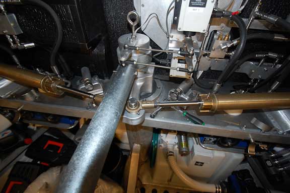
The FPB 64s are fitted with emergency tillers, the main purpose of which is to lock the rudder on center when hove to behind a parachute anchor. The two inch schedule 40 steel pip (galvanized) slips over a projection on the tiller to which the hydraulic cylinders attach.
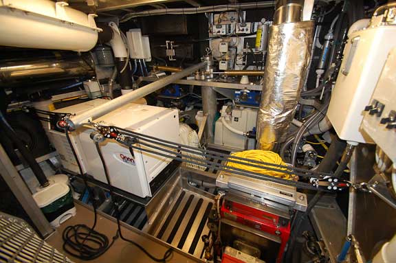
The tiller is positioned and locked in place using relieving tackles.
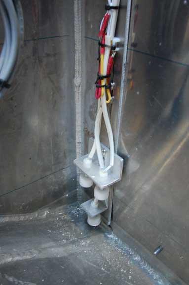
Float switch detail. These operate the bilge pump, high water alarm, and the damage control pump.
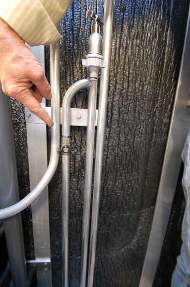
The hydraulically driven damage control pump requires the seals to be wet. The valve feeds fresh water from the ship’s pressure system to the pump.
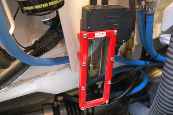
A Murphy oil level gauge. The upper and lower pointers indicate the range for the oil level outside of which the alarm sounds.
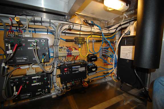
Electronics black boxes in the basement.
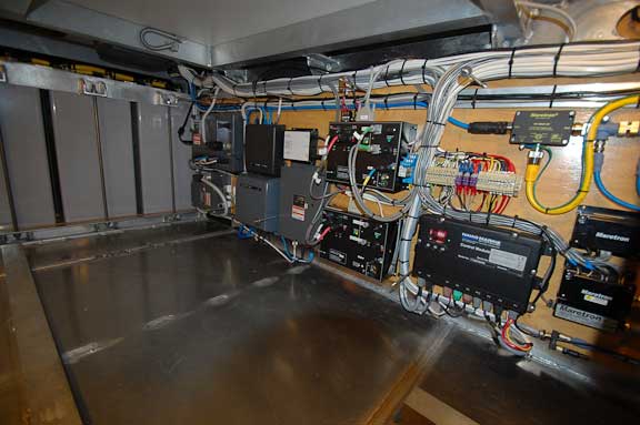
Ease of access equals reliability, simple installation, and efficient changing when the time comes to upgrade.
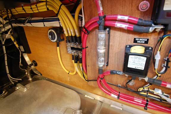
Still in the basement, negative buss bar (yellow wire) and positive fuse with protective cover.
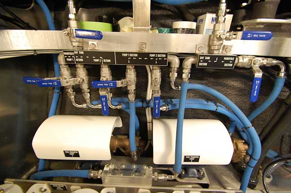
The fuel system in the engine room looks complex but is quite easy to operate.
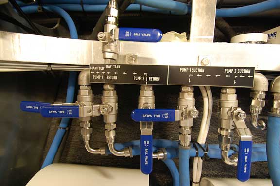
Select pump one or two and turn the suction and supply valves on.
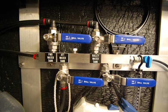
Watermaker output manifold.

Loading software onto the ship’s PC in the office.
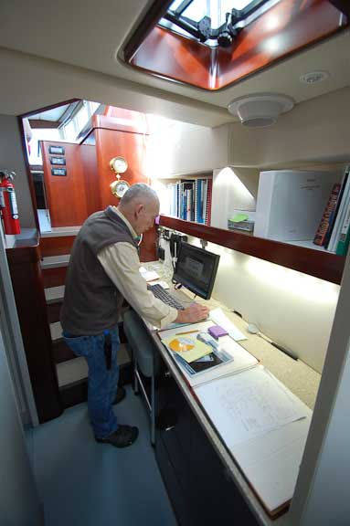
Lots of work space. Reference data and ship’s manuals are stored on the shelf above the desk.
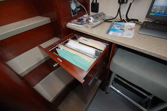
File drawer, a cruising luxury.
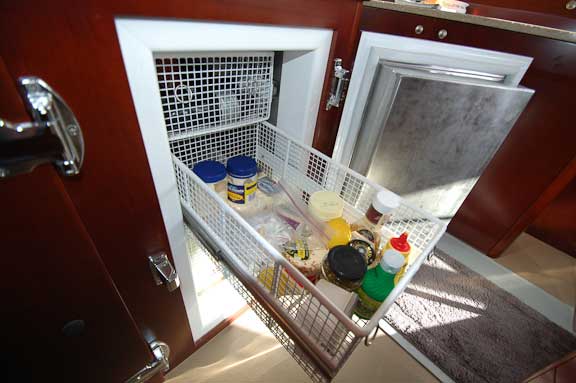
Basket system in one of two fridges (the other has shelves).
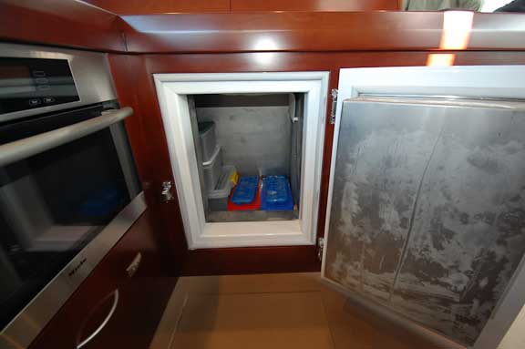
The galley freezer (another is in the basement) extends outboard (to the left in the photo). Note the double gaskets.
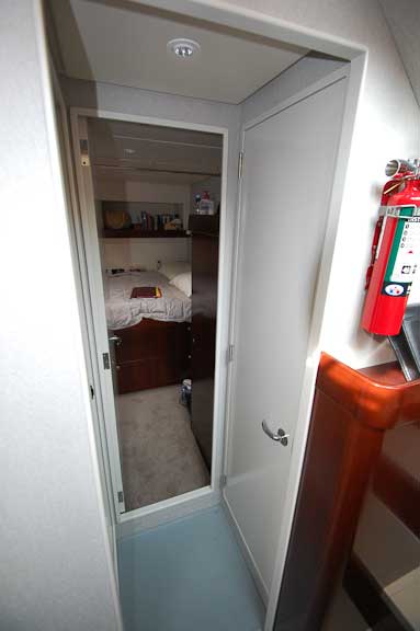
Hallway to the aft port cabin. The cabin door has been moved outboard, leaving half the hanging locker in the cabin and half accessible from the office.
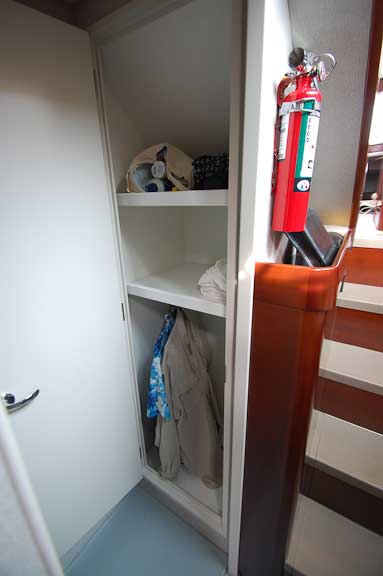
Right now this locker is used for clothing and personal items, but it could be a great place to store camera gear, office supplies, files, etc.
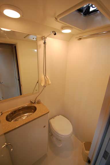
Heads are very difficult to photograph. This partial view of the aft head area will give you a feel for the space. It works well.

September 6th, 2010 at 8:05 pm
Hi Steve,
I’m curious about the black Blue Sea battery switch to the left in the 8th image.
What is a switch in the negative line for? I’d say switching the negative of a circuit alone is odd.
Which standard are you following for the electrical and machinery systems of these vessels? (ABYC, IEEE, ABS etc.)
Nice to see that you have chosen to use Yellow Jacketed cable for the negative battery cables. Is this universal for the whole vessel? I know it can be difficult to get some types of cable with yellow instead of black conductors.
Cheers,
David
September 7th, 2010 at 4:05 pm
Hi Dave:
Good question. The switch is installed between the main DC negative distribution and the single point on the hull/structure where the DC negative attaches. The switch would typically left in the “on” position. There is no switch between the DC negative battery post and the DC negative distribution.
The yellow jacket on DC negative is used as “universal” as possible/practical. Some manufactures included leads or proprietary cabling do not follow this scheme.
The boats are being built to comply with Maritime New Zealand standards, but ABYC standards and practices are often the guiding light for systems and electrical.
As a side note, all panel DC circuit breakers are single throw, double pole, switching both positive and negative legs.
Todd Rickard
January 26th, 2011 at 12:17 pm
About the hydraulically driven damage control pump: Is it possible to use it as a firefighting pump (with additional attached hose) for firefighting (other boats) or repelling boarders?
January 26th, 2011 at 5:32 pm
Hi Rick:
The damage control pump can indeed be used for fire fighting. However, the valving required introduces a level of complexity that could lead to problems if the valves were set t he wrong way. So doing this, or not doing it, must be carefully reasoned.