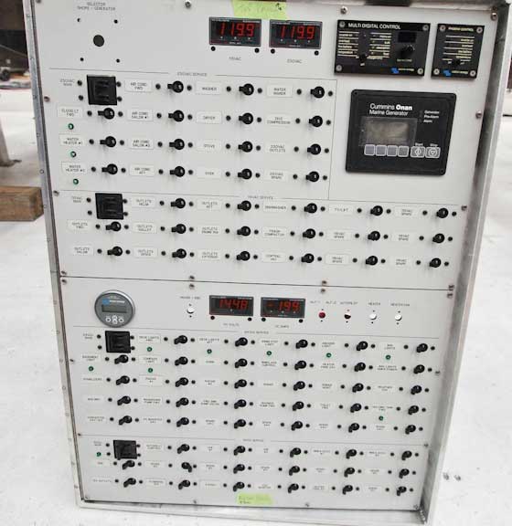
We’ve got a new batch of photos covering the electric panel details which we thought you might find of interest. We’ll start with the panel adjacent (to starboard) of the main helm.
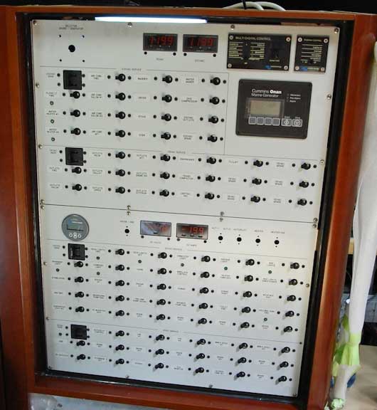
This includes all the AC breakers and source controllers, and the DC breakers which you may want to operate while on watch.
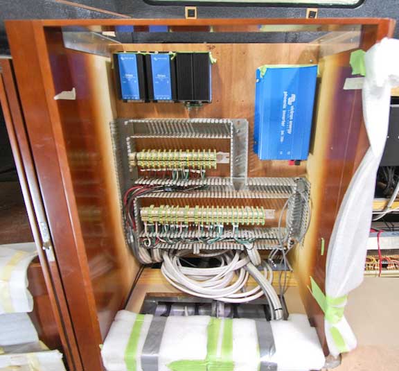
The inside of the locker to which this forward panel attaches is shown above. It is fully wired, and awaiting the panel and its pigtails.
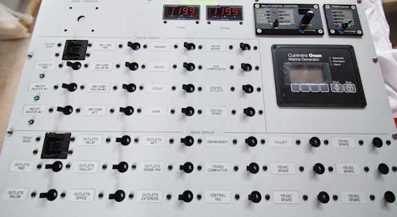
The upper portion has the AC breakers, 230V on top and 115V (this yacht is destined for the US) on the bottom. In the upper right corner are the inverter controls. The right hand control is for the light load (2500 watts) inverter for 115V gear. Next to it controls the three stacked inverters which deliver 7500 watts to the 230V side. The genset panel is below this. On the left there are three green LEDs as reminders that the electric heater coil(s) and/or bow flood light are switched on.
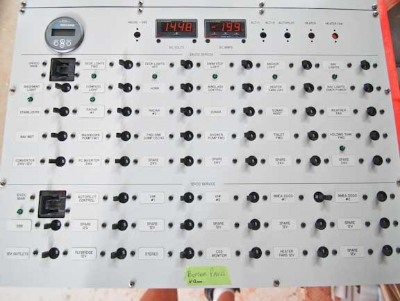
The DC portion is shown here. 24VDC is above and 12VDC below. LEDs are present where reminders are appropriate (for running lights as an example).
Finally, a photo with this panel set on its hinges into the furniture opposite the helm.
There are lots of spares in all four segments for future use.
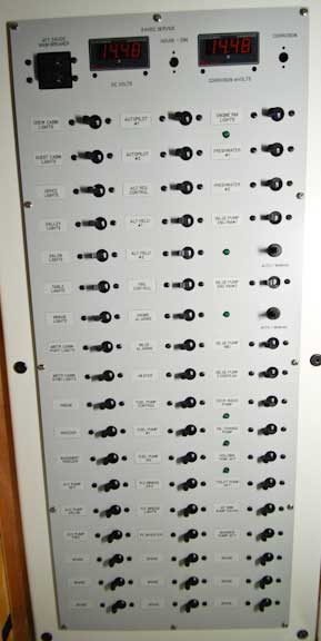
The main 24VDC panel is located at the aft end of the starboard side office. These breakers will rarely be operated as the gear they control is typically on (except for items like the oil change pump).

Access to the back is through a removable panel on the bulkhead).
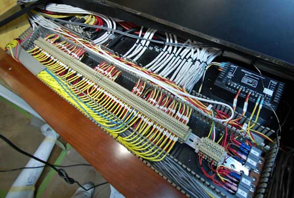
The various items which the breakers control terminate at these busses under the starboard bunk. The breaker panel pig tails then connect to the buss terminals. When changing or adding gear over time (or double checking wiring faults) this approach will save lots of time. It also looks cool.
Posted by Steve Dashew (January 25, 2010)
January 25th, 2010 at 8:41 pm
Wow .. unbelievable installation. Thank you for posting this.