.jpg")
Last week the engines were dropped onto their beds for the final time, and it now becomes possible to get a sense for how well this layout is going to work.
To begin with, the logic of the use of space in the aft end of the FPB 78 series is a bit different. The higher freeboard, slightly further forward engine placement, together with a deeper canoe body, make available additional volume above the engine room sole (walkways) for placement of equipment that in the past required more length. This reduces engine room length and creates the lazarette space aft, which is going to be one of the coolest features of the FPB 78, in the eyes ofyour humble correspondent.
The lead photo is taken down low to show the space between the engines. Sole height will be about the same as in the accommodation deck forward, and even with the underside of the heat exchangers on the engines.
.jpg")
Still at the forward bulkhead, looking down here into the unobstructed sump area (which means easy to clean).
.jpg")
The camera is in the starboard forward corner looking to port. The opening in the bulkhead center left is into the lazarrette. At the right bottom of the photo you can see a horizontal stiffener running across the bulkhead. The engine room sole is around this level.
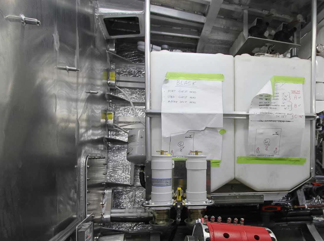
Looking over the starboard engine towards the forward starboard corner. The combination of higher topsides, lower engines, and our hull flare creates extra width up high. This allows placement of systems outboard while preserving room between them and the engines for walkways, inspection, and maintenance. The soft patch in the bulkhead is for access outboard of the shower. The opening at the top is one of two additional air vents for either passive intake or for use when fans are over-pressurizing to exhaust hot air.
The remotely controlled fire dampener also allows us to close these vents when in cooler climates andat lower engine power settings.
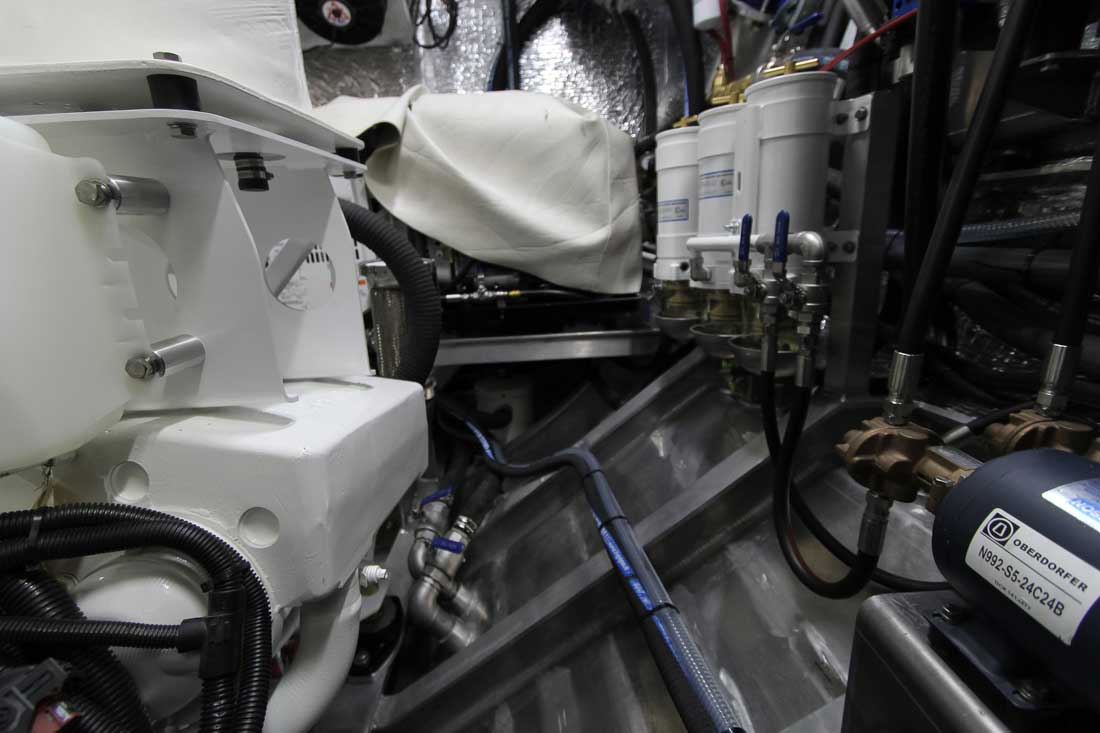
The camera is just above the sole level (which is at the bottom of the heat exchanger). We are on the port side looking aft. The genset is under the cover near the aft bulkhead. Filters on the engine are just to our left but not shown in the photo. There is room to get at everything on the engine.
.jpg")
A close up of the alternator now installed and ready for wiring. Theraw water strainer design, aside from having substantial capacity, provides a wet loop start for the raw water pump, which will make life easier for the raw water pump impeller and seals.
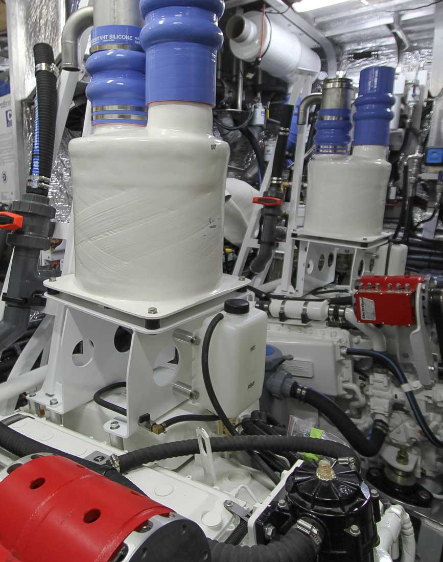
We are fitting both aqualift and mufflers for maximum exhaust noise attenuation. The aqualift is mounted high, which allows the muffler to be located just under the deck. The run of the exhaust reduces risk of back flooding when laying at large angles of heel during a grounding (if we forget to close the exhaust valves).
.jpg")
The thrust bearing and Cardan (U) joint are over-sized for the normal operating speed and loads of the FPB 78. These are sized for commercial duty based on the three to one reduction gear and 330HP/2600 rpm engine. Conservative at full engine output, they are extra conservative for the 75HP we expect will be the average thrust required per engine at 11.5 knots for propulsion. To give a sense of scale, the prop shaft is 2.5”/62mm diameter.
.jpg")
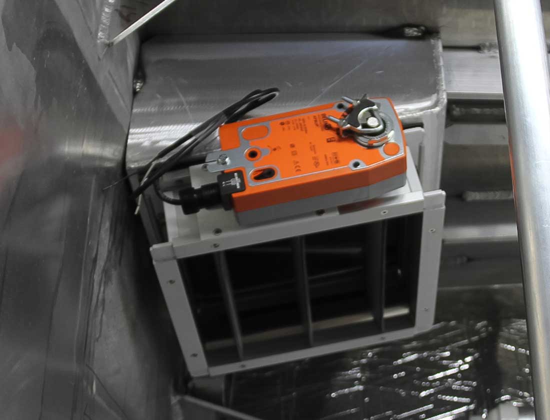
The FPB 78 has a pressurized engine room ventilation system, utilizing three Delta T 1400 CFM DC fans at the aft end of the engine room. The fan base is hinged for access to the fire dampener mounted on the opposite side. The cross sectional area of the air vent is sufficient for proper ventilation without fans if the door is left open as it is in the photo.
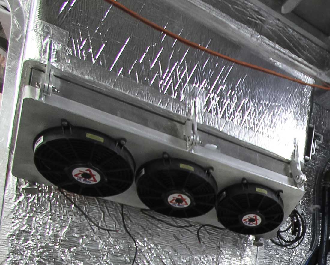
With the fans in action–shown in the closed position above–we expect they will help to provide a cooler engine room. In addition, they will reduce engine room noise escaping to the outside.
.jpg")
We will close with a small but important detail. The pumps are connected to the plumbing system using sections of flexible hose, with an easily removed mac-union at the end to reduce the hassle of replacing pumps.
Posted by Steve Dashew (July 23, 2015)