
You are looking at the business end of what will become an enormously strong bow structure on FPB 97-1. This is the centerline girder, or stem bar as it is commonly known. It is 40mm thick here, and when joined by the two 12mm topside plates will be a total of 64mm thick, or 2.5″.

Another section of the stem bar showing it prepped for welding together.

Sections of topside frames. Note the notches for systems runs.

Tank/hull assembly jig. The hull is being built in sub sections, to be later joined together.

Note the top plate (under the sole), margin sections, and framing are all in place.

Bulkheads before local stiffening has been applied.

More hull/tank sub assemblies.
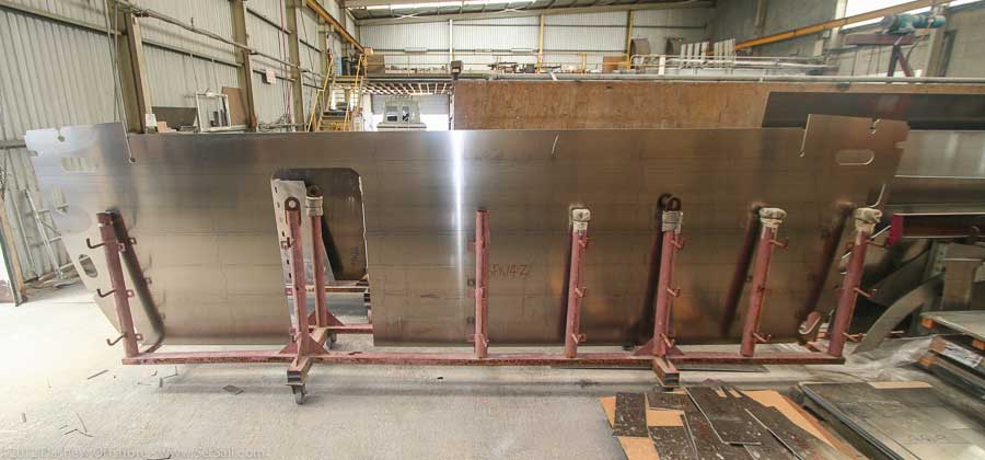
And now scale. That is the bulkhead at the aft end of the owner’s suite. The cut out for the doorway will give you a sense of the size of this bulkhead.
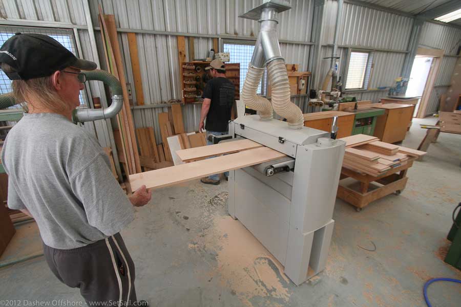
At the same time as the metal fabricators are hard at work, the chippies (carpenters) are in full swing on FPB 97-1.

The master bunk module has already been assembled.

We’ll close with this shot of what will eventually become fiddle rail corners.
Posted by Steve Dashew (October 30, 2012)
October 30th, 2012 at 4:23 pm
Steve, these are the most beautiful pictures that I have seen in a very long time. The 97 will be wonderful!
October 31st, 2012 at 6:13 am
Thanks Michael:
We all share the excitement. It well get better in a couple of months when we start seeing the hull modules assembled.
October 31st, 2012 at 1:53 am
Hi Steve,
Have you moved the position of the access door into the engine room looking at an earlier post looked as if the access was more central in the bulkhead.
Regards
Andrew
October 31st, 2012 at 6:17 am
Oops… that is the bulkhead into the forward suite rather than the engine room.
October 31st, 2012 at 5:59 am
Impressive! Thanks for giving us a sense of the size of this project. Until now it has just been numbers, fascinating, but i had no real sense of the sizes involfed.
October 31st, 2012 at 7:20 am
Hi Steve… using aluminium instead of steel obviously makes these components lighter but with the 97 there’s some serious stuff… are they able to man handle some of these panels around for efficiency or is it all slow mechanical lift?
best,
Warren
October 31st, 2012 at 4:18 pm
Items like the partial frames are easily man handled. Butt he assemblies are lifted with the overhead cranes or fork lifts.
October 31st, 2012 at 12:14 pm
I have seen that all your plates end in radii at the corners as do the cut outs on the frames and bulkheads. Is this a fabrication issue or a structural one? Please can you explain why? Thank you.
October 31st, 2012 at 4:23 pm
The softened (radiused) corners are to reduce stress concentration in these areas.If vou have sharp angles at intersections or corners this is where failure will inevitably occur. Note that some of the cut outs in the frames have doublers which are for the extra loads at the intersection of frame to structural floors (cross beams).
October 31st, 2012 at 11:45 pm
Thank you. we intend to start making aluminium speedboats and this has been a great help.
November 1st, 2012 at 10:03 am
You should add the top photo to your sale’s materials: Not only are you getting a great high-endurance yacht, you’re getting a wacky-big sword! Of course how the insurance companies view a bunch of FPB owners yelling “Ramming Speed!” every time they see something they can cut into pieces might be less good.
November 2nd, 2012 at 8:43 pm
Patrick: brings back memories of our family’s 18ft Grumman lake canoe with 4 young men in it each pounding the bottom with their paddles with that as our battle cry…we never lost an encounter: mass times velocity…wins. Steve, you run a great site! Thanks for taking us along!
November 1st, 2012 at 2:00 pm
It will be interesting to see all the modules come together.
November 3rd, 2012 at 7:34 am
Impressive stem bar bow structure. How are you welding these very thick sections to assure a full penetration weld?
November 3rd, 2012 at 5:11 pm
The welding process includes the right welding equipment, preheating where appropriate, and very good welders/ Of course there are weld x rays to check penetration.
November 6th, 2012 at 2:15 pm
I want one soooo bad. Steve, wonderful site, beautiful craft. I visit every day to see what’s new.
March 6th, 2013 at 9:45 am
Interesting. If you provide the 3d models, some billets and a CNC mill one would be able to build spares at sea.
April 16th, 2013 at 7:18 am
When I was a kid, slowly bobbing along in a Catailna 25 with my father, a Hobie 33 went flying past us. I thought it would be nice to have a Hobie 33 scaled up & built in aluminium. That would be the perfect boat to explore the world. Not long after that I saw some of your early sailing designs & I was 100% hooked. That was my dream for many yrs. Now that I am older & have some health issues that make sailing more work than fun I started thinking a strong,narrow,efficient power boat would be the way to go & turns out you are still building my dream boats. I have finally gotten into a position where,if all goes well,I may actually have the money to seriously make a move towards realizing a long term dream/goal. I have admired your designs for many yrs & I truly hope that,in the not to distant future,you will be building one for us.
April 16th, 2013 at 1:41 pm
Thanks for the positive reinforcement, Shannon:
We have many fond memories of exotic Catalina. Hobie Alter was on the right track with the 33, a really nice monomaran
August 23rd, 2013 at 12:56 pm
[…] The first FPB 97 is well into its construction cycle, and will be sea trialling in the fourth quarter of 2014. In the interim, we’ve put together a detailed look at the thinking behind this Wicked new FPB. For up to date exterior renderings, click here. For the latest construction update, click here. […]
August 5th, 2014 at 1:42 am
I am very curious about how you ‘zinc’ these ships. Presumably you use aluminum anodes, but how many and of what size do you use? I am also assuming that you have a formula as the lovely 64 must have fewer than the imposing 97?
Also, how do you finish the exterior of these hulls before the customer takes them? There are all sorts of welding and grinding and other tool marks showing, but the completed ships have a uniform finish. I read in one blog where you paid a score of teenagers with angle grinders to Scotchbrite the hull after it got somewhat scruffy, but how is it done in the factory?
Thank you for this great blog – hours of enjoyment! I have just begun reading your weather survival book and I am rapt. Thank you for the books too!
August 6th, 2014 at 10:38 pm
Proper cathodic protection depends on many factors including size, aluminum finish, speed, paint system, etc. Where the zincs go is a combination of science and experience. Hull zincs would normally last three to five years. On Wind Horse we changed ours at six years although they had several years more life in them.
September 12th, 2014 at 12:46 am
Thank you for your reply.
I own a 52′ aluminum ex-Parks Canada supply boat. She has proven herself in fairly rough waters by plying the Hecate Straits for 5 years while she looked after the out stations for the Gwaii Haanas park on the former Queen Charlotte Islands, now Haida Gwaii. Hence my interest in aluminum boats in general and yours in particular. My boat has 28 zincs scattered around her keel and running gear, probably something I should have revealed in my first post but in my own defence, I had just discovered that you answer questions!
Can I please ask you again, how do you get such a lovely smooth finish on your completed boats? Mine has an assortment of dents, acquired in battle and none of which (so far) have my name on them!
I recently had the pleasure of seeing Sarah Sarah at her berth in Pender Harbour, my first real sighting of one of your lovely boats. I just watched some of the videos of their rough water prowess and they make mine seem a blunt object indeed. Thank you again for answering these questions.
September 15th, 2014 at 2:08 pm
Howdy Ken:
Those fair topsides are a combination of designed shape, plating thickness,framing, and a large dose of boatbuilding skill.